First preamp build (312), from scratch, high pitched noise!

GroupDIY Audio Forum

Help Support GroupDIY Audio Forum:

This site may earn a commission from merchant affiliate links, including eBay, Amazon, and others.

thebigkevdogg

Member
Joined
Jan 10, 2014
Messages
5
Hi All!

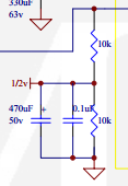
First of all thanks for taking the time to hopefully help a newbie who probably just did something stupid! I'm building a standard 312 circuit with some Yamaha input transformers/op amps I came across from a pm1000. I'm going without an output transformer, and using the post-op amp logic from the JLM BA kit schematic, just a 51 ohm resister and 470uF cap in series to pin 2 with a 10K resister to ground from pin 2 as well. Same for pin 3, but all originating from ground.

I'm powering it all off of a 48v power supply which I made a little circuit to give me a 24v rail as well. I'm wiring the 24v to the common of the op amp, gnd to V-, and 48v to V+. Otherwise it's pretty much a standard 312 circuit.

Anyway, I think I've screwed something up as I'm getting a high pitch whine/noise that is unbearable. Otherwise the circuit, including the gain knob seems to work. I see about .02V from GND to output pin 2 which I figure might be a clue that something has gone amuck. I also get a little spark when I connect my power. The noise is not present until after I connect power. It is definitely amplifying the signal a ton.

Here is a sound sample:
https://www.dropbox.com/s/xevsriu1rnvady7/312_clone_noise.wav

When I zoom in on it in pro tools it seems to be pretty random.

More specifics:
Input transformer: Yamaha GA8027
Op amp: Yamaha NE 80100

Thanks so much for taking the time to read this and help. I don't really know where to start debugging.

Kevin
 
feedback? 
layout related?
pics might help
are d.c. readings correct in situ?
"02v reading" ac ? dc ? referenced to GND (+24vdc "common" or 0v)
what happens when input is shorted?

what happens when 'volume resistance is opened? shorted?

might something be connected in correctly regarding the 'artificial 0v'

 
shabtek said:
feedback? 
layout related?
pics might help
are d.c. readings correct in situ?
"02v reading" ac ? dc ? referenced to GND (+24vdc "common" or 0v)
what happens when input is shorted?

what happens when 'volume resistance is opened? shorted?

might something be connected in correctly regarding the 'artificial 0v'

AHA! When working through your suggestions I found that opening the volume control did stop it, but also cut the signal. I then tried connecting the other end of the volume control to +24V instead of GND and it both works and is mostly quiet. There is still a tiny amount of whine/noise, but I'm not sure if that will go away when it's off of my workbench and in a proper enclosure. See anything else obviously wrong with my schematic?

Schematic as implemented and pictures here.: http://imgur.com/a/RPy75

Now for your other suggestions:

* feedback? If you mean regular mic feedback then no, it happens with no mic connected.
* layout related? hmm, maybe. I'm doing it on a solderable breadboard, layout in the above imgur link
* are dc reading correct in situ? Everything seems good but I'm not sure where to look. One interesting note is that before I added R7 in my schematic (10K resister from XLR2 out to ground) I had about 20V DC on XLR2 referenced from 0V/GND.
* the 0.02V reading was DC referenced from GND. As noted above, this was 20V DC before I added R7.
* shorting input doesn't do anything
* as mentioned opening the volume control kills noise and signal, shorting did nothing
 
feedback like: big voltage from output getting back to input and being amplified again∞...perhaps due to layout/proximity.

24v diode may not be best.
would it be better reversed at 0/-24 input? and/or have 'shunt' diodes to be sure 48>24 > 0

is the opamp known good?
'noise' could be emitted from switching power supply/balast etc. proper screened enclosure and grounding input xfmr case will help that.

are the rails clean ?

  keep crackin'-- what you are up to is DIY...so you are in the right place.
 
shabtek said:
feedback like: big voltage from output getting back to input and being amplified again∞...perhaps due to layout/proximity.

24v diode may not be best.
would it be better reversed at 0/-24 input? and/or have 'shunt' diodes to be sure 48>24 > 0

is the opamp known good?
'noise' could be emitted from switching power supply/balast etc. proper screened enclosure and grounding input xfmr case will help that.

are the rails clean ?

  keep crackin'-- what you are up to is DIY...so you are in the right place.

What's the best way to check for feedback issues? Unfortunately I don't have any scopes or anything, just a multimeter. Likewise for the cleanliness of the rails. I'm using this power supply:

http://www.jlmaudio.com/shop/index.php?_a=viewProd&productId=80
"48v 520mA 25W SMPS that is fully MEPS (Green energy rated) that can run on 80vac to 250vac without switching."

I'm using the circuit from the top right section of here to create a 24V rail:
http://www.jlmaudio.com/Baby%20Animal%20Mic%20Pre%20with%20JLM14%20with%20JLM99v%20or%20Hybrid%20on%2048v.pdf

I recorded a new little sample showing how much better it is, but there is still some whine. Of course this is completely unshielded at the moment on my workbench so I don't know how much will go away with a good enclosure. Note that the first time I break to let you hear the noise, the noise is amplified by 36db. As you'll also hear there is another sound introduced when I unplug the mic. This noise isn't present when power is disconnected. Finally, when I plug the mic directly into my interface at comparable volume there is no audible noise/whine so that's not the problem.

audio clip: https://www.dropbox.com/s/3q5nyng6r1wgvxr/312_clone_noise2.wav

A few remaining clues that there is something wrong:
* spark when I connect power
* 0.028V DC from gnd to XLR out pin 2 when xlr disconnected, goes down to about 0.02V DC when the xlr is connected to my interface (all of this is with power on and a mic connected to an input)

Also I must admit I'm a little clueless on how to best set up the diodes or if they're even necessary. I have 25v zeners, 100v zeners, plus 1N4001/2/4/5/6's. Any suggestions welcome, especially with explain it like I'm 5 specifics :).

Thanks so much for your help!!
 
I notice on your schematic that the output drain resistor goes to 0V. In your circuit this should really be 24V. A small point and not one that is likely to be causing your problem.

I think we should look at your 'little circuit' that produces the 24V from the 48V as this is a potential source of feedback/instability. Can you post its schematic?

Cheers

ian
 
ruffrecords said:
I notice on your schematic that the output drain resistor goes to 0V. In your circuit this should really be 24V. A small point and not one that is likely to be causing your problem.

I think we should look at your 'little circuit' that produces the 24V from the 48V as this is a potential source of feedback/instability. Can you post its schematic?

Cheers

ian

Thanks Ian. For the "output drain resistor" are you referring to R7? If that goes to 24V then won't I have 24V DC across pins 1 and 2 on the XLR output?

Here is the 24V schematic (from here: http://www.jlmaudio.com/Baby%20Animal%20Mic%20Pre%20with%20JLM14%20with%20JLM99v%20or%20Hybrid%20on%2048v.pdf ). The line coming in from the top right is 48V, "1/2v" is 24.

uGcCS6f.png


Thanks,
Kevin
 
OK, the JLM schematic makes it clear what is going on - they are using a 48V phantom supply so they are forced to use its 0V as the overall zero volts. Not ideal but it will work. Ignode my remark about R7.

The 10K/10K pot divider that is central to the 'little circuit' is probably the problem. This is designed to provide a half supply , ac decoupled voltage to provide a bias voltage for op amps operated from a single supply. This works with most op amps because the do not need a high current path to the mid rail voltage.  The odd thing about your schematic is the terminal labelled 'com' that is connected to 0V (24V) so that 'com' presumably means common. Op amps do not normally need such a connection - this may be a weird DOA that does. However, looking at other threads here about this DOA the circuits all look pretty standard. The other common use of the abbreviation 'com' in op amp is for compensation - so if this is a regular op amp type circuit then you should not connect this to 24V and this may be the cause of your problem. You might like to try disconnecting the com terminal and seeing what happens.

Cheers

ian
 
can you power it with a regular linear bipolar supply? I suspect the problem is a combination of no chassis/unclean power rails
 
I'm pretty sure that I am supposed to wire up the "com" terminal of the DOA as indicated. The JLM board layout does that, and every API 312 schematic I see online has "COM" coming in connected to 0v (although in my and the JLM case it's 24v).

That said, I have good news and bad news. The good news is that I now have great sounding clean preamps!!!! The bad news is that I don't really understand WHY, and voltages and such don't seem quite right.

I tried using phantom from another channel of the interface I'm plugging the pre into and it worked, sounded great, and no noise. The thing is once attached, the phantom would go from 48V down to about ~18V. I then decided to try running the existing PSU through a voltage divider before attaching it to the board, thus running it at 24V, with another (the old "little circuit") divider to create a 12V rail. When I do this, it works, no audible noise. The same voltage drop happens though, and I'm getting only 12V out of the first divider (and 6V) out of the 2nd. When the first divider is detached from the preamp I get the 24V I would expect.

I just tried using smaller valued resisters in my divider and I got the voltage to stay closer to the expected voltage (I was using 2 10K's, just tried 2 1K's). It generated more heat though.

Any idea why I'm getting this voltage drop? Should I just smile that it's working and stop asking questions??

Thanks again for all of your help! The end is in sight!
 

Latest posts

Back
Top