dustbro
Well-known member
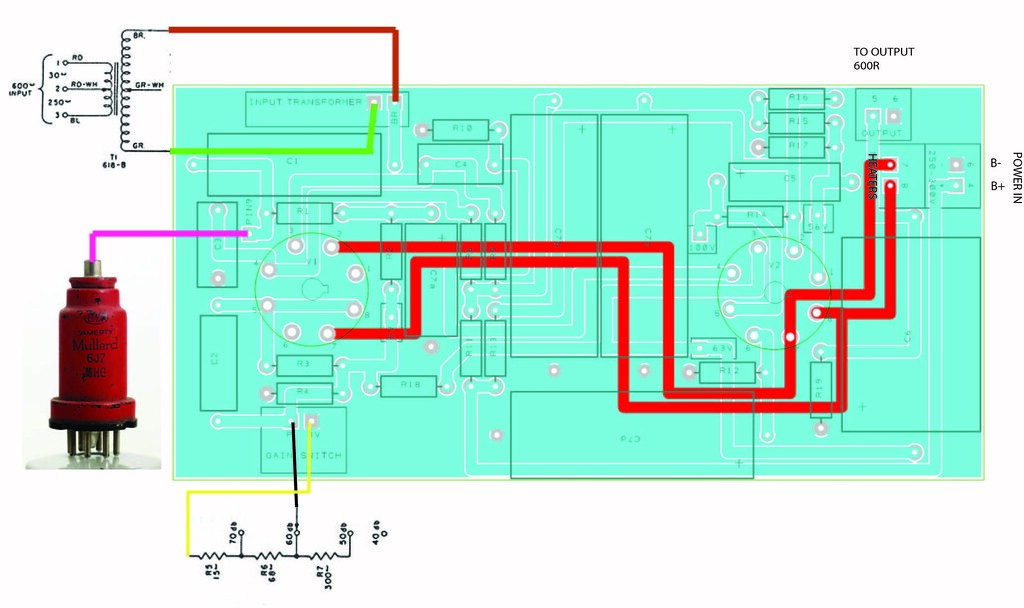
I'm trying to select an input transformer for this project.
http://www.cinemag.biz/mic_input/mic_input.html
Would the CMMI-10PCA (150: 15K) be a good choice? I'm not really sure what a "mic to grid" transformer is.
Any suggestions on an output transformer? I'm assuming that this circuit is unbalanced at the moment.
http://www.cinemag.biz/mic_input/mic_input.html
Would the CMMI-10PCA (150: 15K) be a good choice? I'm not really sure what a "mic to grid" transformer is.
Any suggestions on an output transformer? I'm assuming that this circuit is unbalanced at the moment.