dmnieto
Well-known member
It seems that my post on the thread was not seen so I will do a separate thread. Short story, I had built a relay board to add some functionality in the stereo linking, basing it on the design from Purple Audio. I was going to offer the Gerbers to the community, but Purple Audio vetoed it.
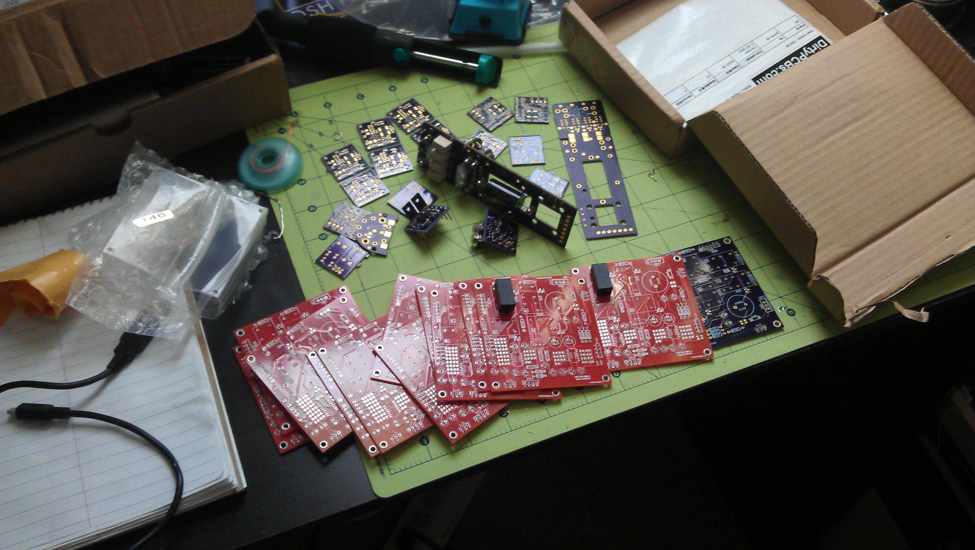
I still have 13 boards with the last prototype. I offer them for free, heck I will even pay postage for the guys in the US, it is just sad seeing them unused. I wont re-spin the design, share the gerbers or do additional runs. So this is it.
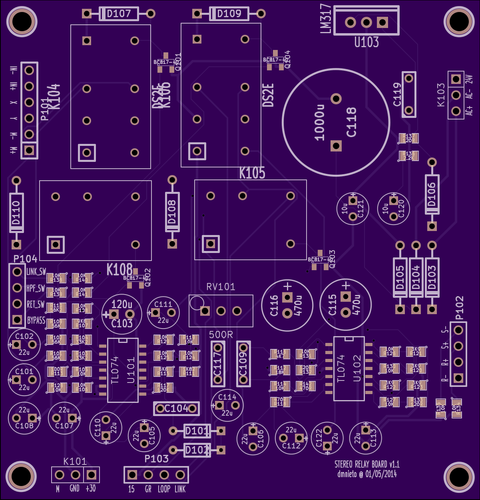
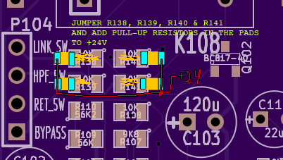
For the "lucky" people that get them, I will provide the BOM and some instructions about how to wire it properly (I should have added many more GND pads), also it has SMD parts... LOTS of them, but they work, and if you want the challenge... Some people may not need all the features. You need two for a stereo build.
The only thing I ask in return is that when you finish the design you post a picture of it.... so who is taking?
I still have 13 boards with the last prototype. I offer them for free, heck I will even pay postage for the guys in the US, it is just sad seeing them unused. I wont re-spin the design, share the gerbers or do additional runs. So this is it.
For the "lucky" people that get them, I will provide the BOM and some instructions about how to wire it properly (I should have added many more GND pads), also it has SMD parts... LOTS of them, but they work, and if you want the challenge... Some people may not need all the features. You need two for a stereo build.
The only thing I ask in return is that when you finish the design you post a picture of it.... so who is taking?
dmnieto said:So finally I managed to finish my dual rev D stereo with the following modifications:
- True bypass with relays.
- Addition of the super-slow attack switch and the ratio 2 (it has ratios 4, 8, 12, 20, SLAM and 2).
- Buffered metering.
- Side-chain high-pass. (with relay switch)
- Side-chain send-return. (with relay switch)
- Link mode (with relay switch)
Oh boy this has been difficult... I had to design and re-spin boards, prototype, sort out routing and grounding schemas, drill more holes than I thought possible, and solder lots of small SMD parts,... But yeah! It works and sounds great!. The feeling of actually designing even a part of it by yourself is very rewarding when it finally works
With the mess of routing I made I am surprised there is no noise, or motor-boating, or oscillation ( even If I know the relays help)... I have to thank mnats, mike, dan and everybody in this thread for their help and for making something like this available to everybody.
Unfortunately Purple Audio vetoed the sharing of the schematics and the gerbers of the add-in board (as it is their right), but I still have 12 (unpopulated) boards around here if somebody else wants it (but I warn, this has been the most difficult build I have ever done... oh my god the smd parts). I can also describe how I added the 2:1 ratio to the rotatory version (having 5 ratios + slam) and the simple fix that is to add the super-slow mode.
So pictures here:
My wife is really digging the combination of super-slow attack, fast release, 2:1 ratio and hpf sidechain as a master bus compressor")