wtmnmf
Well-known member
This looks like a candidate: http://www.supertex.com/pdf/datasheets/CL520.pdf


JohnRoberts said:I would be inclined to stay away from mains wiring.
Rochey said:The switches won't be switched mid performance anyway (and if they are, the compressor settings that they effect will make a difference in the sound)
Rochey said:I'm back to thinking - run my micro off a small regulator from 30V constantly, and switch the LED's from the 30V supply in the same way I'd switch a relay (an NPN transistor and a resistor).

Rochey said:Question is - do you think people would mind putting an extra PCB in their product, and tapping the 115VAC from the primary of their main transformer to another pcb?
jdbakker said:Your call, but odds are better that a design's supply won't mind having 10mA leeched than up to 40mA.Rochey said:I'm back to thinking - run my micro off a small regulator from 30V constantly, and switch the LED's from the 30V supply in the same way I'd switch a relay (an NPN transistor and a resistor).
jdbakker said:Rochey said:I can see how that could work if I was making a bar-graph or something, (i.e. LED1, or LED1 and LED2, or LED1,2 and 3, etc. But how to I control each of them separately?
Let me paint you a picture.
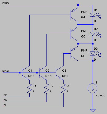
When IN1 is logic high (3V3), a negligible current flows through the collector of Q1 and base of Q4 (tens of nA for modern small-signal transistors at temperatures that are comfortable to humans), Q4 is off for all practical purposes, and all but maybe a few uA of I1's current flows through D1. When IN1 is logic low (0V), enough current flows through R1 and Q1 to turn Q4 on. Now (almost) all of I1's current flows through Q4, D1 is off. Repeat for all other LEDs, you can switch each on or off independently.
Select the resistor value so that Q4/5/6 hFE times resistor current is much larger than I1, but have resistor current much smaller than I1. This is because resistor current ends up flowing through Q4/5/6 base and emitter; for longer chains this means that LEDs higher in the chain get more current depending on how many lower LEDs are switched off. I'd say 10k is a good starting point.
JDB.
[picking BC557C's or other high-hFE transistors for the PNP parts doesn't hurt, although I suspect any modern part will do]
Rochey said:Why do q1,q2,and q3 need to be common base?
Why not common emmitter?
Rochey said:The main difference between this and previous simulations is that my Q1,2,3 had the resistors on the input to Base, rather than connected between Emitter and Ground.
I still don't understand why that made such a difference.
Enter your email address to join: