fully passive (no gain) pultec topology eq

GroupDIY Audio Forum

Help Support GroupDIY Audio Forum:

This site may earn a commission from merchant affiliate links, including eBay, Amazon, and others.

dfuruta

Well-known member
Joined
Apr 8, 2010
Messages
237
Hello,

I've been reading this board for a while now, and learning a lot, but this is my first time posting.  I am working towards building a passive eq based on the pultec schematics on the Gyraf website.  I would like to keep it totally passive–my plan is to have a transformer-balanced output that can be plugged into a mic amp for make-up gain.

This is what I am planning:  this is updated to reflect the conversation below
1024x768


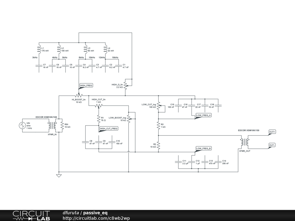
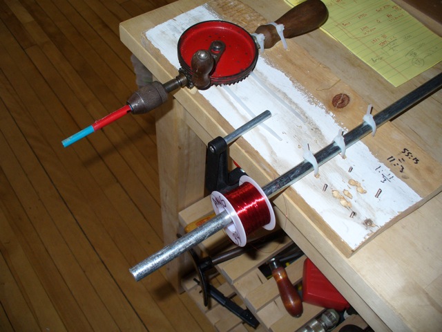
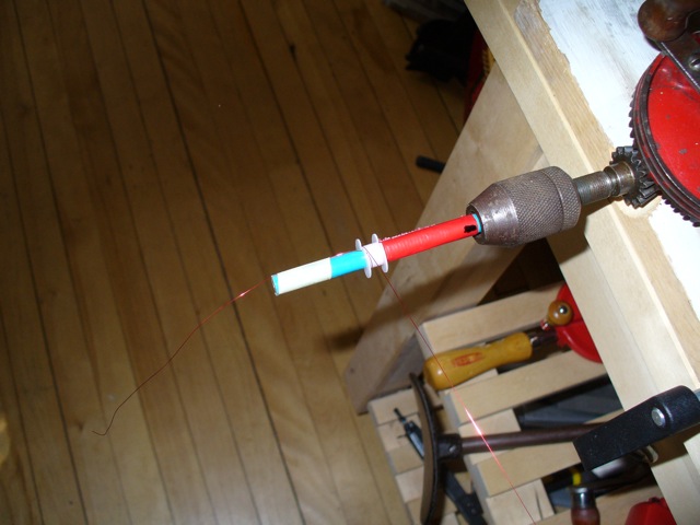
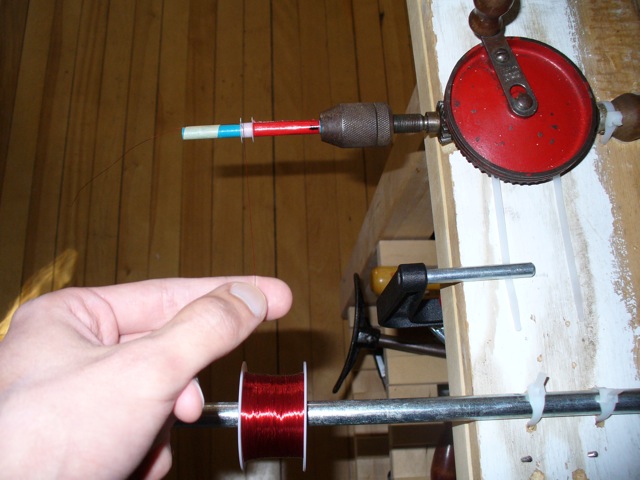
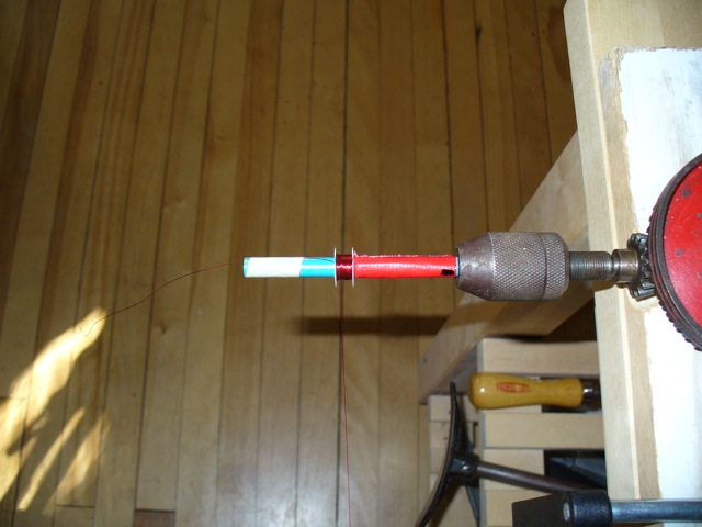
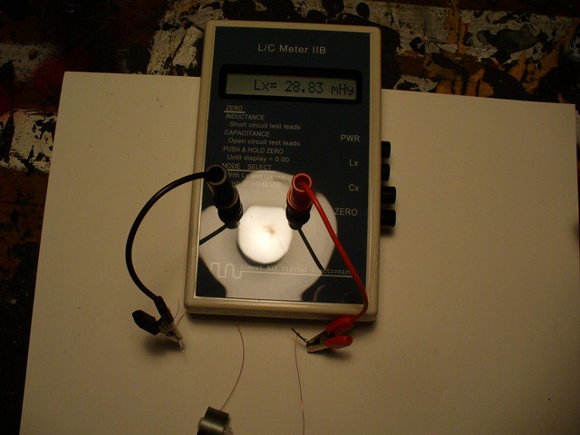
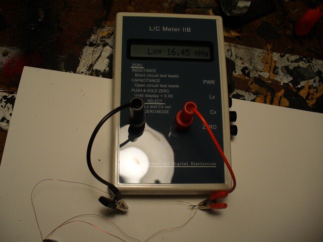
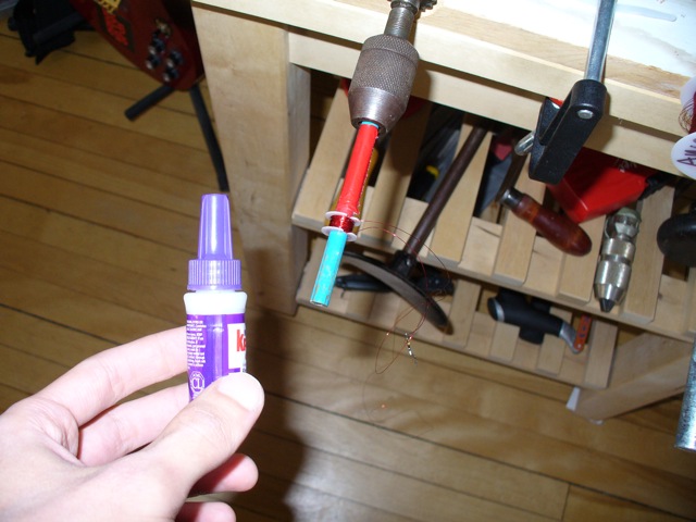
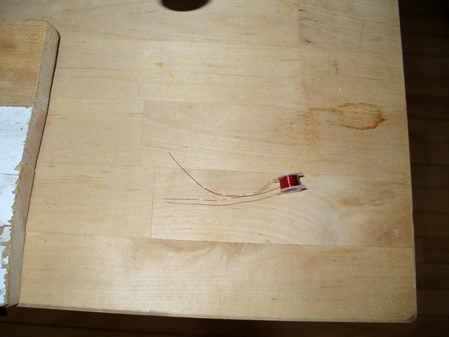
I will be winding the inductors myself.  Got that part more or less figured out, at least!

Before I go and drop the money for the components, I wanted to post and see if there are any glaring problems.  I'm very much still a student when it comes to electronics, and it's totally possible there's some huge mistake.

If I am correct, this will need around 45dB of gain to get back where it started.  This is higher than I'd like, but I'm not sure if there's a way around it while still keeping reasonable input and output impedances.  I'm also not sure if a 600 ohm output impedance is a little high to feed into a mic amp.

I would be very grateful for any criticism & critique!
 
For better loading a 7:1 or higher output transformer will present a lighter load at the output 49x2K=98Kohms, assuming a 2K impedance preamp input. With only a 4:1 it would look like 16x2k=32Kohms. If you also use a 1:1 600ohm for the input the gain loss would be roughly the same as in your plan. I have tried something similar with well spec'd transformers and it was fine, but I would use a purpose built gain stage if at all possible.
 
MatthisD said:
For better loading a 7:1 or higher output transformer will present a lighter load at the output 49x2K=98Kohms, assuming a 2K impedance preamp input. With only a 4:1 it would look like 16x2k=32Kohms. If you also use a 1:1 600ohm for the input the gain loss would be roughly the same as in your plan. I have tried something similar with well spec'd transformers and it was fine, but I would use a purpose built gain stage if at all possible.

That's a good point, thanks.  Maybe I'll use a 10k:150 output transformer.  I think I'd like to keep some step down on the input, though, since a 600 ohm load seems a little low for modern gear.  At this point, a few more dBs might not really matter, anyway...

From your experiments, did you find that noise was the biggest problem?
 
dfuruta said:
That's a good point, thanks.  Maybe I'll use a 10k:150 output transformer.  I think I'd like to keep some step down on the input, though, since a 600 ohm load seems a little low for modern gear.

Have a look at the g-pultec schematic, 1:1 input with a 10K load. A 1:1 input with a 2 or 3K load may work for you.

Well it was just to test the filter circuit without the gain stage. By ear, there was no noise at all really but this was at low speaker levels. Lundahl input and a Jensen DI transformer were used plus the preamp so a total of four transformers in the chain. So depending on what you use, frequency response could be level enough or it could be a rollercoaster before touching the EQ controls.
 
MatthisD said:
Have a look at the g-pultec schematic, 1:1 input with a 10K load. A 1:1 input with a 2 or 3K load may work for you.
I hadn't seen that (whoops!), thanks.  Seems like a 10k:10k transformer terminated with 10k might be the way to go.  I was worried that the impedance might drop too low at some frequencies if the transformer were 1:1, depending on how the eq is set, but after calculating it with some different settings, maybe it's not so bad*.  Maybe it's worth trading a lower impedance in the very high frequencies (no lower than the original, anyway) for a reasonably higher level overall for what I'm trying to build...

*if I'm not screwing up my calculations, the impedance at 16kHz roughly = the 75ohm resistor with the high boost maxed@16kHz, sharpest Q, and the high cut maxed@5kHz, everything else flat.  But, I think it's in the triple digits for more realistic situations.  Who knows, maybe some of the resulting distortion is what people liked about the original.

Well it was just to test the filter circuit without the gain stage. By ear, there was no noise at all really but this was at low speaker levels. Lundahl input and a Jensen DI transformer were used plus the preamp so a total of four transformers in the chain. So depending on what you use, frequency response could be level enough or it could be a rollercoaster before touching the EQ controls.

Good to hear!

If I use a 10k:10k input and 10k:150 output, I need around 45dB makeup gain.  That seems pretty reasonable for a mic preamp to do quietly.  And, transformers and their uneven frequency response will be there whether it's active or passive (?).
 
I just went ahead and ordered the transformers from Edcor.  I hope this comes out ok!
 
I built this, and it seems to work fine!  Doesn't seem too noisy using a mic preamp for the makeup gain, and the eq is nice and smooth & seems to work as expected.

There's a weird 2dB peak at 30kHz, for reasons I don't understand–I imagine there's some parasitic coupling somewhere due to sloppy construction, but I haven't tracked it down.  Not sure I really care, honestly.

Thanks again, MatthisD, for your suggestions.
 
good stuff!
Is it built as in your drawing? output secondary centre tap to ground or just a leftover from the pultec schematic?
Can you measure the frequency response without the input transformer, then just the preamp and then the stepdown transformer/preamp combination. If you can it might tell you more about the frequency response.
Matt
 
I did ground the center tap, but after reading and thinking about it a bit more, maybe I shouldn't have!  I'll try it without.

It's within 1dB from 20Hz-20kHz, but then there's that little bump at 30kHz.  Tomorrow I'll poke around a bit and see whether it's the same with & without the transformers.  I was mostly just pleased that it seemed to sound ok, so I didn't spend much time investigating.

I'm thinking maybe I'll try the same thing with the meq next.  A few more inductors, but it seems like more or less the same idea.

Wound the inductors on the 77 material pot cores from amidon, and adjusted the capacitors to get the right frequencies.  I made a little setup with a hand drill to wind.  Those inductors really drift with temperature!  I put one in the freezer for a while, just to see, and the value changed by something like 20%.  Might try gapped cores in the future, as those are supposed to be better.
 
The hf bump is from one of the transformers - can't come from the filter (if it's built as per schematic)

You may want to use a 600:600 input transformer like the original, as the DC resistance of the 10k:10k is rather high in relation to the very-low impedance of the filter (when boosting high, it'll go as low as 75 Ohms worst-case). Coil resistance at the input transformer (and source impedance of external circuit driving the filter) will significantly influence the maximum amount of boost that can be had on the hi-boost knob.

Jakob E.
 
WSM10K/10k DCR = 252/272ohms, do you think lowering the load resistor to 2.7K would be worth a try? Pultec is about 60DCR secondary, 600ohm load. The Edcor has 10 to 20henries approx. so better suited to lower than a 10K input impedance for low frequency response.

Also see:
http://www.edcorusa.com/Content/Plots/WSM10K-10K.pdf

I'm confused that your circuit works with the stepdown output centre-tapped going into your preamp's input unless you have a grounded centre-tap in the Pre too!?
 
try this:
http://powermagnetics.co.uk/calculator.html
Jakob E.
Wow, cool link
I am interested in materials and techniques as well...
Where and what type of cores, wire, etc...
And how to wind and count turns.
 
Interesting!  So the HF bump is from the transformer;  that makes sense, since I couldn't figure out where it was coming from.

With the input transformer terminated with 10k, I still get around 15dB of high boost.  That seems like plenty.  When I calculated it, I got around 18dB, so I can live with 3dB difference.  I figure it might make it a bit easier on the source when the EQ is set for moderate settings.

That worst case impedance is only when it's also cutting the highs, correct?  75ohms seems pretty bad, and so I was considering a step-down transformer on the input.  But I don't imagine that setting happens enough to be a big worry (?)

Thanks for that calculator link!  I was just estimating, and then measuring and adjusting.  I'll actually take some pictures of the method I used for winding and put them up here.  I'm still at the point where it's kind of a crap-shoot, but it's easy enough to just adjust the capacitor values if the inductor is in the right neighborhood.
 
OK, here's how I've been winding inductors.  I'd really like to hear better ways to do any of it.

I'm using the 77 material pot cores from Amidon Corp.  They ship with a bobbin, the two halves of the core, and a nylon screw/washer/nut.  Say I want to wind a 22mH inductor.  I go over to the Amidon site, look up the AL (they use non-standard units, so watch out), and calculate that the wire needs 87 turns.

I built a jig using some scrap wood & a metal rod, and an old hand powered drill.  I have a bunch of these drills;  this one is kind of crappy.

7982960941_c2038ba3e4_z.jpg


The drill has a gear ratio of 3:11, so that means I need to turn the handle 24 times.

I'm using 34 awg magnet wire.

I put the bobbin on a mandrel I made from a piece of a pencil and some tape, tape the wire down to the mandrel and wrap it around the bobbin once.

7982960865_d24f49db79_z.jpg


I tension and guide the wire with my fingers.

7982960819_a8d014e8ea_z.jpg


Once it's wound, I tape down the loose end so the windings don't slip.

7982960745_414a40d6f6_z.jpg

7982966116_4c908dfbf9_z.jpg


Solder on temporary leads for measuring & put the inductor together.  The fumes from the magnet wire are really nasty, so I've rigged up a fan & some cardboard to pull the smoke away from my face.

7982960639_dd8d0cff32_z.jpg

7982960583_f975df28d4_z.jpg

7982965940_55dde1c2c3_z.jpg


I've found that the inductance tends to increase in value after I've glued the windings.  So, I want to unwind it until it's actually a bit low.  It's also possible to adjust the inductance somewhat by tightening the screw more or less.

I've got an AADE meter that works up to 150mH.  Higher than that, I use the oscilloscope & signal generator with a resistor as a voltage divider.

7982965868_b187506cd4_z.jpg


After unwinding it a little:

7982960453_d127225145_z.jpg


That should be ok.  I've found that the value increases by maybe 50% in the end.

I brush the windings with super glue, trim the leads, and set it out to dry.

7982965716_c351bb5a02_z.jpg

7982960299_9287484598_z.jpg


Once the glue has dried, I'll wrap some tape around the windings for good luck, and then put it together permanently.

I don't really know if this is the proper way to do it;  it was pretty hard finding good information on this stuff.  The ones I've wound *seem* to work fine, but I don't know how they'll do in the long term.  Like I mentioned above, these cores aren't gapped, and the inductance swings like crazy with temperature.  I just ordered some gapped cores, and I'll probably try those in the future.
 
You could, but I didn't.  Multiple taps makes it harder to get the values correct...I figured the cores are cheap enough that it was fine to just use separate inductors.

EDIT:  to clarify, what you'd do is wind the first value, pull out a loop to solder to, keep winding for the second value, pull out another loop, so on.
 
Heres what I've learnt of this black art of pot core winding with centre-bolt.
The lower turns for a given inductance the more extreme the value can change due to other factors like bolt tension. When measuring the inductance it will be different measured an inch outside of the core than a foot, after winding a few I started burning off the wire coating as close as possible to its exit from the bobbin to take a reading before adjusting turns.
Tapped inductors;
If the AL value for the core is given at 3660, and your 100 turn test winding measures 32mH then pick 3500(or whatever your instinct decides) as your AL value. Calculate the turns required for inductance at each tap and wind the coil to your calculations ignoring measurements taken at each tap other than to check that its there or thereabouts. This method should give an inductor with proportionate error from intended inductance rather than one tap too high and the next tap too low kind of thing and 'should' get values within 5% or less of intended.
If winding more than one of the same inductor, wind 100 turns on a bobbin and assemble with the core and measure L. Move on to another core, if the L is different on that one with the same 100 turn bobbin try different combinations of core halfs to get the best matched pair. Hand tighten the nut as tight as you can as a torque guide.
I still haven't found the best way to mount these pot types but the provided washer and nut first, and then another washer and nut to mount it to something seems best so far. Going much tighter than hand-tight on the nylon nut risks ruining the threads, using a metal bolt risks breaking the core if not careful. Bonding halves together is something I haven't tried.
Another thing to consider is using a wire gauge that will best fill the bobbin for the total number of turns rather than a smaller gauge with empty space surrounding the coil.
 
As far as mounting, I drilled some holes in a piece of perfboard and strapped the inductors down with cable ties, and then poured on some hot glue.  Looks awful, but seems pretty solid.  I just ordered some spring clips with pins on the bottom, so that should make it easier next time.

What have you used for leads?  This time, I soldered the magnet wire to bits of paperclips, and then soldered those to the perfboard.  Not ideal, but I was kind of short on ideas.

It's kind of amazing that these things work at all!  There's a lot of trial and error involved...
 
Back
Top