Fun fuzz circuit

GroupDIY Audio Forum

Help Support GroupDIY Audio Forum:

This site may earn a commission from merchant affiliate links, including eBay, Amazon, and others.

Gus

Well-known member
Joined
Jun 3, 2004
Messages
5,269
Location
n
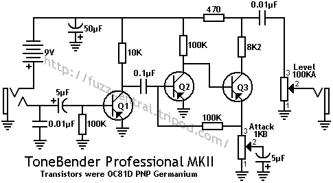
The circuit in the link is a fun circuit I simmed and built based off the Supa/TB2 circuit. Changing the Ge for Si transistors.

Note the collector voltages often the web gets things wrong like the bias to 4.5VDC nonsense. Sometime 4.5VDc is OK.

Someone posted a youtube link to their build. It sound very close to my build

pay attention to my posts about how it is different than the first post screenshot.

https://www.diystompboxes.com/smfforum/index.php?topic=114210.0

Gus
 
Note that because Q2 emitter is grounded, the leakage of that Germanium transistor is significant wrt the bias point. So a Si Q2 will bias very differently when you consider that 100uA of leakage is normal for Ge transistor and 4.5V / 100K = 45uA.
 
squarewave

I don't understand you post. Read Electric Warrior's posts in this thread and others look for the real voltage readingshttps://www.diystompboxes.com/smfforum/index.php?topic=92104.0

Look at Q2 220k collector resistor I used to keep the 100K bias/feedback resistor value that works with the first stages output resistance to set part of the gain

This is a Si take of the TB2/Supa type fuzz. I used the voltage readings that people measured from real TB2 to rework the circuit for Si.
Q1 and Q3 around 8VDC and Q2 as low as possible for Si
Q1 and Q3 are close to cutoff and Q2 is close to saturation.

I dislike building with Ge transistors yes they can sound good but so can Si
 
Ok. If you're just experimenting and think it sounds good, then go with that.

But if you're trying to make a circuit that mimics the Tone Bender, you might consider the differences and consequences of using Silicon transistors in place of Germanium.

Here's another difference: Q1 in the original TB circuit isn't biased through the base at all. It's biased with leakage current. You can't do that with a Silicon transistor. The way you compensated for that can be improved on I think with a largish resistor from the collector to the base and then remove the 180k and 1k and change the 15k back to 100k.

mkIIschematic.gif
 

Latest posts

Back
Top