G-PULTEC problems, please help!

GroupDIY Audio Forum

Help Support GroupDIY Audio Forum:

This site may earn a commission from merchant affiliate links, including eBay, Amazon, and others.
If i want to transform potentiometers of a dual mono pultec into stepped switches, is it as easy as using the 1x12 lorlins, adding resistors to it (like in the pqd2) and connect it?

i found these pcb's: http://diy-tubes.com/index.php?route=product/product&path=59&product_id=167

might that work?

thanks
 
jon83 said:
Hi all,

Can someone tell me what the resistor values on the Don Audio filter board are? On the original they're marked as 1k, 1k, 10k, and 75r, is that right? If so, what do they correspond to, R1, R2 etc. Cant seem to find this anywhere online.

Probably a bit late but for anyone else needing them they are:

R1 = 75R
R2 = blank
R3 = 10K
R4 = 10K
 
petermontg said:
What I am trying to do is just to control the input into the SRPP.

Any Ideas wold be great.

Best
Peter

You could replace the 10k resistor in front of the SRPP (between filter pcb in and ground next to 220n coupling cap to ground) with a potentiometer to attenuate the signal.
 
Hey guys,

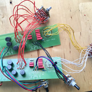
i built a pultec with stereo potentiometers and dual gang switches from a kit i bought off a member here. But the high section (boost & attenuation) doesn't do anything on both channels..
Low section works as expected. i checked the wiring and couldn't find any loose connections.
Could you give me a hint where to look ?
Otherwise this eq is working fine.

thanks
Ansgar
 
gyraf said:
High boost and high cut are two entirely different functions, so it's probably more that one error. Maybe switch miswireing?

Jakob E.

Oh okay! alright, i'll check.

thanks for the persistent help  :)
 
gyraf said:
High boost and high cut are two entirely different functions, so it's probably more that one error. Maybe switch miswireing?

Jakob E.

Now i completely rewired the 3 switches, replaced the 4 filter boards but nothing changed  :-[
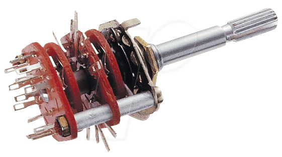
I am not using lorlin switches mounted on the pcb but these front panel mounted dual gang switches:
RS2212.png


I put the marked with 1 as the first position of each switch, that should be correct - or not?
Does the  high freq selection switch need connection from the poles to the pcb? It seems they are only connected to each other.
 
i am absolutely confused where this might come from. i used two completely different filter boards and wired all switches from the beginning but still the high section doesn't do anything...  :-[
Is there someone who might have experienced the same?
I am clueless  :-\
 
Ansgar, is this a dual 2x6 rotary switch for sure (4 pole connections) ?
As you didn't fit all wire connections where the joins were made on pcb, you did all (5 per side, 10 for stereo) corresponding joins at the switches poles and throws directly ?
 
Harpo said:
Ansgar, is this a dual 2x6 rotary switch for sure (4 pole connections) ?
As you didn't fit all wire connections where the joins were made on pcb, you did all (5 per side, 10 for stereo) corresponding joins at the switches poles and throws directly ?

hey, yes it has 2 poles per channel so 4 in total and 6 positions.
I made all the connections which are needed on the pcb. when no lead was going from the switch on the pcb then i didn't wire it. hope this makes sense..

Like said there is no problem at all with the low section, this is what makes me wonder :-/
 
For Hi-boost frequency selection, deck 1, pole A and throw 1...6, pole B and throw 7...12. Deck 2 hooked up the same.
You joined throw 1 with 2, 4 with 5, 8 with 9 and 11 with 12 and you joined pole A with pole B ?
(hookup of low section and Hi-cut is different from Hi-boost)
 
Harpo said:
For Hi-boost frequency selection, deck 1, pole A and throw 1...6, pole B and throw 7...12. Deck 2 hooked up the same.
You joined throw 1 with 2, 4 with 5, 8 with 9 and 11 with 12 and you joined pole A with pole B ?
(hookup of low section and Hi-cut is different from Hi-boost)

yep, exactly what i did
 
Back
Top