G-PULTEC problems, please help!

GroupDIY Audio Forum

Help Support GroupDIY Audio Forum:

This site may earn a commission from merchant affiliate links, including eBay, Amazon, and others.
I bought 2 power trafos for a stereo g pultec project years ago with following specs from micandmod (https://micandmod.com/hardware-parts/223-power-transformer-pultec-eqp-1a-gyraf.html):

Voltages, primary: 0-115V, 0-115V
Voltages, secondary: 0-9V/1A, 0-220V/50mA, 0-11V/500mA

can these be used to power 2 pcb's? i am worried about the 11V compared to the 5V secondaries offered with this one:
https://www.don-audio.com/g-pultec-power-trafo-sec-220v-9v-5V
 
weiss said:
I bought 2 power trafos for a stereo g pultec project years ago with following specs from micandmod (https://micandmod.com/hardware-parts/223-power-transformer-pultec-eqp-1a-gyraf.html):

Voltages, primary: 0-115V, 0-115V
Voltages, secondary: 0-9V/1A, 0-220V/50mA, 0-11V/500mA

can these be used to power 2 pcb's? i am worried about the 11V compared to the 5V secondaries offered with this one:
https://www.don-audio.com/g-pultec-power-trafo-sec-220v-9v-5V

I used the G9 one from Don Audio without any issues in  stereo version.
Don't cheap out on the shielding....... Save yourself a headache,
 
So, I did a little mod on mine today.

A little switch to bypass the whole mid boost section connecting back to the 0mh pin which leads back to the lowend boost and high freq cut.

Unit sound so much better when using the lowend only, really opens it up and you can have lowend boost for days.
Going to put it under scope tomorrow see how its reacting.

Switch connecting is
Pin 1 (bottom) - 0mh
Pin 2 (middle) - output from SRPP
Pin 3 (top) - to filter input.

Ground stayed the same connect straight to filter.

Have fun, if anyone try's it.

Best
Peter
 
Hi all!

Im still having issues with my build. The output is really low and thin, I can hear the filters are working its just that the signal sounds very broken, thin and low gain.

Ive checked my xlr wiring and terminating resistors are correct. Im using wired Alpha switches and LL5402 in/out. Don Audio PT.
I read that I should recalculate the big watt resistor value for the don audio PT, currently I have one thats suggested in the bom. Is there a chance my tube is broken? I havent actually measured what voltage the PT is giving to the tube.

IMG_20170619_133112_fotor.jpg
 
What toroidal are you using? Check your voltage after the 3K3/2W. I doubt your tube is broken. There are 3 voltage to power the SRPP. 
 
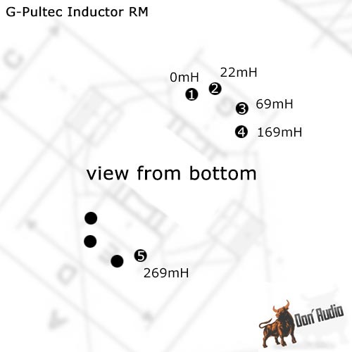
Hey guys, I'm having problems figuring out how to wire the RM-8 inductor by don audio..
https://www.don-audio.com/G-Pultec-Inductor-RM8-22mH69mH169mH269mH

the connections on the pcb are 2 per inductor but the rm8 combines all 4 together with one output for each value.
so which pin should be used for the second connection of each value?

Inductor-312mh-155mh-78mh-39mh-26mh_2_b2.jpg


I hope you get what I mean..

thanks
Ansgar
 

Attachments

  • Bildschirmfoto 2018-03-28 um 20.43.37.png
    Bildschirmfoto 2018-03-28 um 20.43.37.png
    37.5 KB
weiss said:
Hey guys, I'm having problems figuring out how to wire the RM-8 inductor by don audio..
https://www.don-audio.com/G-Pultec-Inductor-RM8-22mH69mH169mH269mH

the connections on the pcb are 2 per inductor but the rm8 combines all 4 together with one output for each value.
so which pin should be used for the second connection of each value?

I hope you get what I mean..

thanks
Ansgar

The pic you attached

You see how one step on the switch connects to the end of two inductors at a time?

You are just tapping into windings on a single inductor and setting them up to switch in series instead of using single inductors.

Gustav

 
Gustav said:
The pic you attached

You see how one step on the switch connects to the end of two inductors at a time?

You are just tapping into windings on a single inductor and setting them up to switch in series instead of using single inductors.

Gustav

ahhh now i get it.. thanks Gustav!
Ansgar
 
Hi all,

Can someone tell me what the resistor values on the Don Audio filter board are? On the original they're marked as 1k, 1k, 10k, and 75r, is that right? If so, what do they correspond to, R1, R2 etc. Cant seem to find this anywhere online.

 
Hey guys.
I experienced some weird behaviour with my new g pultec. Everything works except in one position (60Hz) of the low frequency rotary switch (2x6) it is louder than the other selectable frequencies (20-100Hz). I checked the wiring for mistakes but i couldn't find an explanation for this behaviour. any ideas? is the switch broken?? it also makes "sound" during switching, whereas the other switches just mute during switching...

thanks,
Ansgar
 
Louder as in: if you test it at 60Hz signal - or louder like in "all frequencies are boosted"?

First is a property of eq's :) - last points to a defective capacitor or connection..

Jakob E.

 
gyraf said:
Louder as in: if you test it at 60Hz signal - or louder like in "all frequencies are boosted"?

First is a property of eq's :) - last points to a defective capacitor or connection..

Jakob E.

second one!
let me try to explain: in the low boost section i can select (rotary)

20Hz, 30Hz, 50Hz, 60Hz, 80Hz, 100Hz

When i switch to 60Hz the whole signal gets boosted like 5 db's or so. A single frequency is not the problem but the overall loudness difference. but only on this switch position, all the other positions i can select in the low section work like expected. I resoldered the whole switch connections so that leaves a dead cap?
 

Attachments

  • IMG_2162.PNG
    IMG_2162.PNG
    129.9 KB
gyraf said:
..the one associated with the problematic step on the switch...

sorry for being so dumb. I found the problem. It was indeed a bad connection.
Thanks Jakob!
 
just built another stereo pultec! the device is alive and working but:

the hi boost freq setting at 3k gives me 1k, 1k equals to 2k and 2k gives me 3k in the analyzer. so the frequencies are actually switched around..
I double checked the values and they match the schematic, any ideas how i could find the error ?
which one is the cap that needs to be switched  ???
 
gyraf said:
The capacitors in series with the inductor and Q-pot controls the frequencies of high-boost

Smaller capacitor => higher frequency

Jakob E.

thanks, you solved it!
it was indeed too small ::) ::)
 
Back
Top