G-PULTEC problems, please help!

GroupDIY Audio Forum

Help Support GroupDIY Audio Forum:

This site may earn a commission from merchant affiliate links, including eBay, Amazon, and others.
Neily said:
That looks amazing....

Could someone explain to me how this can be built using only 1 toroidal? I see some gpultecs with 1, some with 2 and I'm confused. Sorry if it's a stupid question, I'm new....

I'm going to be building mine soon... I'd prefer to use only 1 if i could.

Hi Neily, thank you very much :)
the power trafo is a custom wounded trafo especially for the g-pultec project.
I tryed some different other trafos and came to the point to run a custom trafo production that fits perfect to this project.
You can get this trafo direct from me or at my lil online shop http://don-audio.com/g-pultec-power-trafo-sec-220v-9v-5V_2
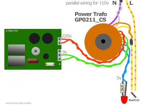
I build my third g-pultec now and with this trafo there are no noise or heat problems cause the 9v are better for the regulators than 12v. At the end you need 6,3v for the tube so 9v is the perfect match. 5v is a seperat winding for the led or 5v light bulb. This trafo can also be fixed horizontal and vertical in a 2HE case cause of its small size.
be careful with this high voltage project. But this is sounding awesome and worth all the work.
 
who said:
Neily said:
That looks amazing....

Could someone explain to me how this can be built using only 1 toroidal? I see some gpultecs with 1, some with 2 and I'm confused. Sorry if it's a stupid question, I'm new....

I'm going to be building mine soon... I'd prefer to use only 1 if i could.

Hi Neily, thank you very much :)
the power trafo is a custom wounded trafo especially for the g-pultec project.
I tryed some different other trafos and came to the point to run a custom trafo production that fits perfect to this project.
You can get this trafo direct from me or at my lil online shop http://don-audio.com/g-pultec-power-trafo-sec-220v-9v-5V_2
I build my third g-pultec now and with this trafo there are no noise or heat problems cause the 9v are better for the regulators than 12v. At the end you need 6,3v for the tube so 9v is the perfect match. 5v is a seperat winding for the led or 5v light bulb. This trafo can also be fixed horizontal and vertical in a 2HE case cause of its small size.
be careful with this high voltage project. But this is sounding awesome and worth all the work.

This PSU looks great... currently gathering info and putting together BOM to start my own pultec project.... couple of questions... do you have a diagram for the PSU which describes which windings are which based on the colors, trying to work out the connections to the gpultec mainboard in my head.... also, any modifications need to be made to gpultec board to accomodate this PSU??? Thanks!
 
@frazzman
here is a diagram how to wire this trafo:


You can also wire it parallel for use in 110v countries.


I used a LED lamp with a 3k9 resistor. If you want to use the original fender 5v lamp bulbs you need no resistor.


all the best
"who"
 
Hi snipsnip,
this is a 600v 6a rectifier (Vishay) that rectifies the ac current of those 220v wires more far away from the pcb to optimize the noisefloor. It replaces the onboard bridge-rectifier that rectifies your ac to dc. DC current does not radiate as much as AC does. So it is better putting +-220v dc into this pcb than rectifieing those 220~ ac on board near to the sensible parts. The 4u7 con and the xformers are very sensible to radiation. There are no problems with 9v ac - it can be rectified on board.
 
Hi G and Who! Thanks for your replies.
Who, looking forward to that g-pultec torroidal.
Btw anyone have know where I can get that 5 volt pilot lamp assembly?
Thanks again,
Chris
 
Where would be the best spot to stuff a VU (and if necessary a buffer)?

Just prior to output XLR?

I've an old Ampex VU that I'm thinking of repainting and adding to the G-pultec if only for some 'ooo aaaah'.

Also, I'm thinking of mounting the tube off of the pcb.  What are any things to be cautious about?
I'd like to mount it in a way to be viewable through a small window similar to how ART does the tube MP.
 
Songguy said:
where I can get that 5 volt pilot lamp assembly?

you can get those Fender lamps from banzaimusic or if you like, i have a lot of them here too. Just give me a mail.
But be careful not to buy those chinese plastic fakes. They should be glass and metal.  :)
 
after some time troubleshooting I have the g-pultec working great with no hums or other issues (so far through a brief vox/bass test) 

The thing is just amazing simply cranking a pre and listening to the noise floor while playing with the knobs.

Used the same power transformer as audiophreak but ended up using a pot to drop down to 6.3. 

I mounted the tube off of the pcb and cut some slits so that it can be viewed while glowing (you cannot really see it so it was kind of a dud idea)

Also, I do have the VU tied to the output XLR but the meter just does a funny dance near zero and only jumps up on loud transients, and then slowly releases back to zero.  If this needle would dance with the level out it would be friggin cool looking.  Anyone care to shed some light on how to configure a VU?

Did all the metal work myself with a 2mm steel Hammond 3RU very very shallow enclosure.  I ended up mounting the power transformer on the back of the exterior of the case.  The front panel is my first and turned out so so.  The VU was a pain in the ass, the metal work in general has been a learning experience.

The only issues I have are with my High Freq 2x6 and High Shelf Freq 2x6, since mounting the board to the front panel these two switches now want to go twice around the horn, so twelve positions.  It seems to still function in this configuration but to no benefit and only confused the hell out of me for awhile.  So that will need to be corrected.

Overall was a good build, would have been smooth sailing if I had just purchased a case.

 
If it is a real VU-meter (AC-reading, internal rectifier), you simply connect it across your output, with a 3K9 resistor in series with the +side of the meter, and it will read 0VU for a +4dBu signal level.

If it's not a real VU-meter, but a DC-reading meter, you'll need to add a diode bridge of four low-forward-voltage Ge-diodes (and hope that sensitivity is somewhere around what you want).

BUT - both these solutions will add distortion to the unit, so better make it switchable.

(I really don't see the need for a VU-meter on a unit like this, other than the good looks)

Jakob E.
 
gyraf said:
(I really don't see the need for a VU-meter on a unit like this, other than the good looks)

Absolutely,  thanks for the tips Jakob... I'm really not sure if this is an AC/DC reading meter, it was cannibalized from an Ampex 1260 reel.  I see no passive components internally, it simply looks like a needle and some coil windings. 

I shall try the 3K9 in series with the + side, I have assumed so far + terminates to pin 2 of the output, and the - side to tie to pin 3?  Thanks for the tip on the switch.

This was my first valve circuit and I cannot thank you guys in this thread enough.  I've learned a lot more about power-supplies during this build than I've ever had to know.

Seeing that GE start to glow amber was very satisfying thanks again to Jakob and everyone who has contributed to this thread.  And especially to audiophreak (I have been stalking your picasa for weeks) I liked what you did with one transformer and I ran with your idea.  Thanks to Kingston for the KISS principle on recommending the simple dropping resistor.

I still need to powder coat my front panel, and airbrush all the pad printing.
 
Micdaddy , Thanks for the kind words ,  Glad to hear of your success  :)
 
  .. on the  " View Window "  for the tube - I've seen a few units with this and found they " Back Light " the tube in the box so it can be seen through the " Window " -  maybe a little 6v incandescent or one of those " Warm " LEDs behind the tube opposite the window ? 

  Congrats !!    .. and lets see some pics  ;D   
 

Latest posts

Back
Top