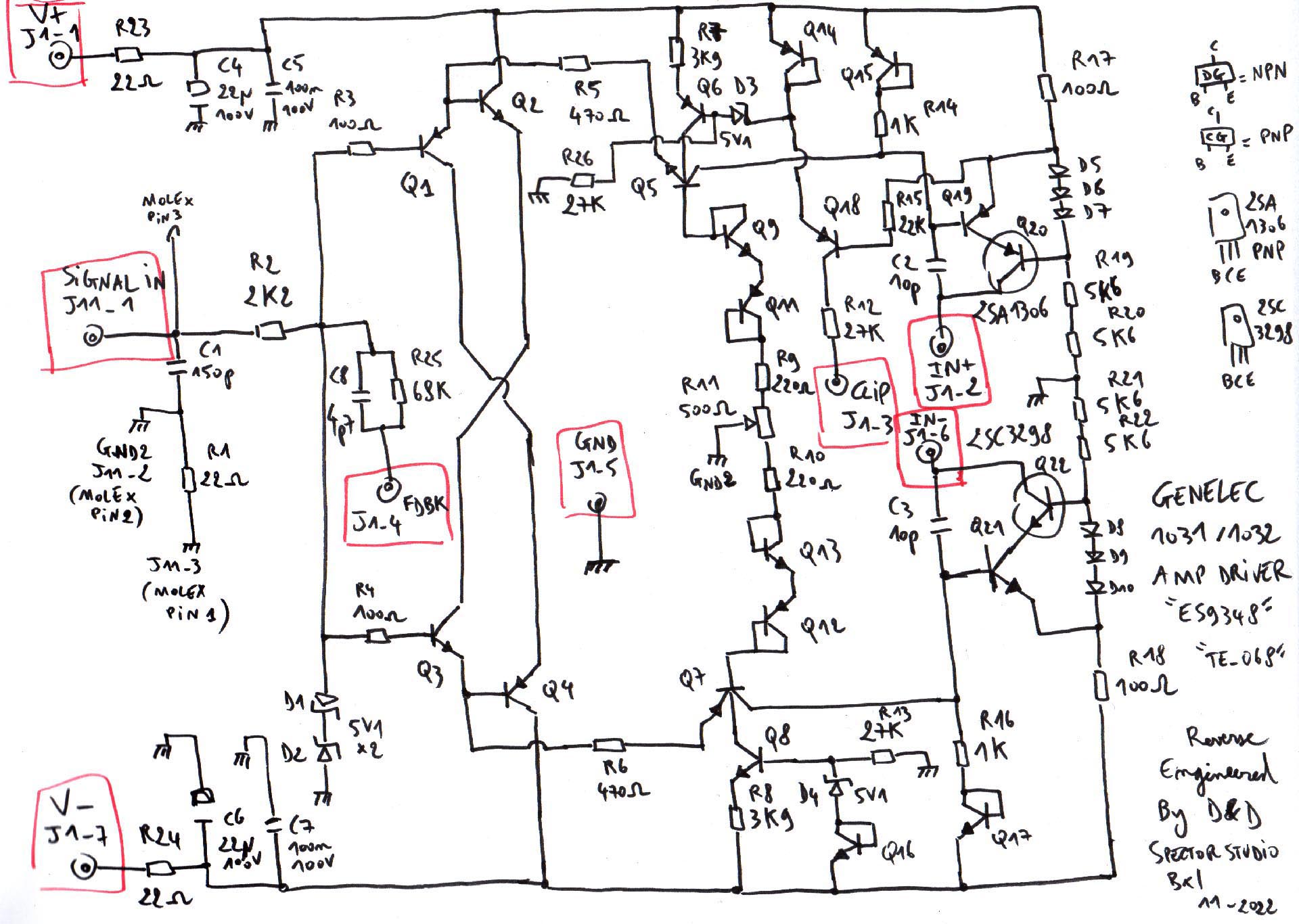
Genelec 1031 Driver cards need repair/help

GroupDIY Audio Forum

Help Support GroupDIY Audio Forum:

This site may earn a commission from merchant affiliate links, including eBay, Amazon, and others.
I have a doubt with the clip circuit, I guess the idea is that when R17 draws excessive current Q18 start to conduct, and spikes above 1V make the comparator IC2A (schematic hereunder) go down and the "clip" led lights up..
I've put the hole circuit in Spice and the simulation doesn't react as expected for the clip indication
 

Attachments

  • 1031 CLIP.jpg
    1031 CLIP.jpg
    143.8 KB
Here are the 2 schematics side by side for a better global vision :

a5cfd1511f990385cafe212e9e35c6ba.jpg


52579-12a6ae27bcb04401b85f0a5ec69f09ff.data
 
Now I did some measurements on an original working 1032, and comparisons with the repaired one :

Bass PA frequency response (brown is original, green is repaired) :
PA BASS COMPARE.jpg
Crossover Bass line output response (purple is original, blue is repaired), we can see that the difference doesn't come from the PA, as we have the same mismatch in the crossover (probably the capacitors 5 or 10% tolerances) :CROSSOVER BASS COMPARE.jpg

Treble PA frequency response (purple is original, pink is repaired), crossover line out is the same :PA TREBBLE COMPARE.jpg

Finally I did measurements with a mic in front of the speaker (same place same mic position, 10cm from acoustic center), green is original, red is repaired :
ACOUSTIC MEASURE.jpg

And here the blue graph is the PA Block of the original 1032 mounted on the repaired speakers :ACOUSTIC MEASURE 2.jpg

Feel free to comment.
 
After checking and repairing other things on the 1032 I was working on, like soft-start muting circuit problems and clipping indication circuit pbms, I did a final calibration (Red is original working one, and Green is the one I've repaired).
So I can now confirm that my retro-engineered boards are 100% efficient !

1673041846914.png
 
After checking and repairing other things on the 1032 I was working on, like soft-start muting circuit problems and clipping indication circuit pbms, I did a final calibration (Red is original working one, and Green is the one I've repaired).
So I can now confirm that my retro-engineered boards are 100% efficient !

View attachment 102625


WOW, Amazing and Impressive work.
First on the circuit tracing, that alone is a lot of work and hard to do with SMD components.
Then you designed your own replacement PCB using proper size components, outstanding.

Frequency response looks Great.


Congratulations
 
Hello everybody ,

a friend ask me help for check a non working Genelec 1031 monitor ,
after some test (as indicated in the service manual)
seem that the problem is on woofer driver card, fitted with smd components ,

any help about how to proceed for right test and repair the card is welcome ,
thanks in advance.
S.
I draw a schematic of the modul, I have here two 1031 with non working bass part. So if you need any help I send it. I appreciate when there is someone who can help me. regards Mike from Munich
 

Attachments

  • PA-Treiber_Bass.jpeg
    PA-Treiber_Bass.jpeg
    607.3 KB
I draw a schematic of the modul, I have here two 1031 with non working bass part. So if you need any help I send it. I appreciate when there is someone who can help me. regards Mike from Munich
Hello Mike, thanks for sharing, I can see few mistakes maybe :
- you have 2 times 3 diodes in series, these are indeed general purpose diodes, all others are 5v1 zeners
- the capacitors on the output transistors are not correctly placed
- few npn transistors are noted pnp and vice versa
 
Thank you.. I´ll check it - it was 2 years ago - since that time these Genelecs are on the shelves, I wish they would run again..
kind regards
 
Hi there! I wonder if this driver card is the same that came in the 1038A amplifier, it looks very similar. I need some replacement cards for the 1038As. Im afraid Ill have to build them too....WhatsApp Image 2024-02-02 at 15.36.47.jpeg
 
Hi there! I wonder if this driver card is the same that came in the 1038A amplifier, it looks very similar. I need some replacement cards for the 1038As. Im afraid Ill have to build them too....
Hi,
Try to check and confirm that these 2 diodes are 5V1 zeners, and that these 2 capacitors are 10p (but it should be) :
1707039781117.png
Then you will have to replace on my board the 2 pairs of 5K6 resistors in series by 2 triplets of 3K9 resistors in series.
There doesn't seem to be here the two 22r fuse resistors in series with the power rails, so you can replace them with a wire on my board or just keep them, I don't think they will hurt.
Also the 4p7 capacitor seems missing here (at the left of the 68K resistor), so you will have to omit it on my board :
1707040092192.png

Also I can't garantee 100% that the boards are the same, let's say 95%
I can't either garantee that it will mecanical fit your PA pcb
 
Last edited:
Hi!
Yes the diodes are in deed 5v1 zeners (actually they are measuring around 5.5V) caps are 10p probably too, I cannot measure them with my meter.

I have only one bad card, it is intermitent poping and when it pops the protection red led from the speaker lights up. strange is that I replace all transistors and all 4148 diodes and the problem doesnt go away. I ordered the zeners to see if thats the issue, if not I think I would buy your PCBs. Thanks for the help!
 
Back
Top