Great River MP-2 , info, schematics & discussions

GroupDIY Audio Forum

Help Support GroupDIY Audio Forum:

This site may earn a commission from merchant affiliate links, including eBay, Amazon, and others.
I wanted to clarify a few things regarding J1-J8 from drawing:

http://www.matt-allison.com/diy/greatrivermp2/GR%20audio%20card%20schematic.pdf

I have made a list and put a bunch of ???????? on the items I wasn't sure about. Pls see below; it would also be great if someone could check the ones without question marks just to dbl check:

J1 audio input
1 input XLR pin 1
2 input XLR pin 2
3 input XLR pin 3

J2 (using JensenJT-13K7-A)
1 white wire
2 red wire
3 brown wire

J3 (using JensenJT-13K7-A)
1 black wire
2 orange wire
3 yellow wire

J4 (1/4" TS jack)
1 "sleeve"
2 connects to 3, unless 1/4" plug is inserted
3 connects to 2, unless 1/4" plug is inserted in which case it connects to "tip"

J5 (1X24 rotary)
1 from switch resistors
2&3 pole

J6 switches
1 ?????????? to J8-5?
2 ?????????? 48V?
3 powers phase reversal relay
4 powers pad relay
5 0V

J7 audio output
1 ?????????? choice of 10 or 20 ohm to output? One for O/P transformer, one for unbal. out?
2 0V
3 ?????????? choice of 10 or 20 ohm to output? One for O/P transformer, one for unbal. out?
4 0V

J8 power
1 ??????????
2 ?????????? B- (what voltage?)
3 0V
4 ?????????? B+ (what voltage?)
5 ?????????? relay power (what voltage?)

Thanks in advance!!

Martin
 
J1 audio input - shielded wire connect ground by i/o connectors only . not on pcb
1 input XLR pin 1
2 input XLR pin 2
3 input XLR pin 3

Primary & secondaries , with hi/lo hot/cold +/- connect as per xfmr you are using , connect ground & shields at i/o bus bar only , NOT on pcb

J2 (using JensenJT-13K7-A)
1 white wire
2 red wire
3 brown wire

J3 (using JensenJT-13K7-A)
1 black wire
2 orange wire
3 yellow wire

Switching d.i. input , you can simply connect 2 & 3 if you don't want the 1/4" jack use two conductor shielded wire , unless it is very short

J4 (1/4" TS jack)
1 "sleeve"
2 connects to 3, unless 1/4" plug is inserted
3 connects to 2, unless 1/4" plug is inserted in which case it connects to "tip"

J5 (1X24 rotary)
1 from switch resistors
2&3 pole

One wire each for polarity & pad relays with a common ground for both ,
and then simply two wires to connect or break voltage for Phantom
[ that makes 5 right ! ?]


J6 switches
1 48v you are simply breaking the connection on / off
2 48V
3 powers phase reversal relay
4 powers pad relay
5 0V

two ouptputs for bal or unbal and their grounds , obviously there will be two connections to feed a transformer , As it is recommended that the main board ground comes from the ground bus at the i/o connectors
you don't need to use the ground on the output , or if sheilded wire ,
connect only at the i/o ground bus

J7 audio output
1 One for O/P transformer in
2 0V
3 one for unbal. out
4 0V

J8 power
1 signal to peak led driver
2 Negative supply to board [ anything over 24vdc my g.r. psu sends 33v
3 0V ground should go to i/o bus ground where chasis & psu ground meet
4 Positive supply to board [ anything over 24vdc my g.r. psu sends 33v
5 Phantom power supply , anything over 48vdc , my g.r. psu sends 66vdc


that is i believe looking at the connectors from left to right

regards Greg
 
Wow, glad I ordered the parts kit! (Thanks Ptown) :thumb: When I checked the transistor part numbers on digikey it seemed like most of them are obsolete or quickly going there. It would be really great to have cross references/substitutes for all the old transistors to keep this breathtaking preamp alive. Does anyone have this? What's the story on 2SK-389?

Thanks,

M.
 
fwiw , i've had no problems with mine and Dan may have had 2 out of 10,000 come back .
[ c'mon everyone what's that in percentage ? ]

In the unlikely chance that you need a sub , then there is one and you
can deal with the lead bending then .........................
if you super worried , paranoid i can get you one , but i can't supply
extras for everyone [ very few left ]

To answer another quetion , i have ran my unbal out at least 100 ft from the stage ,
and the only problem i ever had was with a studio having an ungrounded patchbay


regards Greg
 
Hi OKGB,
I don't doubt these things will probably outlast my ears! :wink: It just seems like no one sells LSK-389C besides Ptown. I get nervous if I can't find what I'm looking for between Mouser, Digi-key, Newark and Allied.

Ptown: are the leads on LSK-389 just spaced differently or is the pin asignment order different as well?

BTW, I got my Jensen JT-13K7ATB's in the mail today. Elma 04-1130's will be here any day now... CANT WAIT!!! :cool:

M.
 
I should finish my other projects first (2xGSSL and 1 p2p LA2A) but I can't resist this one!

I'm starting with the 24 position switch resistor bank.

I recall reading somewhere that position 1 and 24 are not used? Or at least they are not used like the others.

I've reread this entire thread and didn't see anything about this!

Anyone recall what positions 1 and 24 do ?

Thanks

jim
 
Without a stop pin the switch will rotate continuously , and there would be
a no gain pos . otherwise afaik , it's min to max gain

regards Greg
 
[quote author="madriaanse"]
Ptown: are the leads on LSK-389 just spaced differently or is the pin asignment order different as well?

[/quote]

Different package all-together.
 
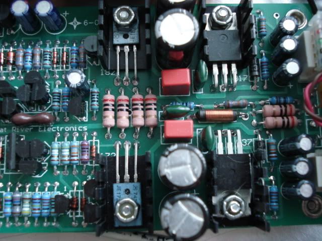
Pix in case it is of any help to builders

regards Greg

Picture099.jpg

Picture101.jpg

Picture100.jpg
 
Does anyone have a picture of the Elma Rotary Switch (not the pcb mount) and the wiring diagram for the mainboard ?

This project is really cool, it went togheter in 1.5h of soldering... what a beautiful board !

Thanks guys !
 
Neeno, do you want the schematic of the Elma switch? The link is in the first page I believe. If not I can send it to you. Let me know.

I've only wired my switches so far. First one took me 3 times what the second one did.

jim
 
Hi Jim... i have the switch schematic, a picture would be great !
As far as i can see there is no wiring diagram for the card, but i think i'll try to wrap it up quickly following the informations on this thread...

I'm sure it would make wiring simple.
 
Its straight forward. I had never done a switch like this but its very easy.

One trick is to have it hanging upside down (shaft pointed up, terminals down).

Line up terminal 1 so its rightmost.

Prepare the first 6 resistors (1 to 6).

Bend them all 90 degrees with a lead bender if you have one (about 1/2 to 3/4 inch from body or more if you prefer)

With needle nose plyers bend the outside bent lead another 90 degrees so that it ligns up parallel to the inner one.

Now cut the outer lead about 1/8" from bend. You should now have a small hook to squeeze through the appropriate terminal.

Once inserted squeeze it on the terminal with the plyers. It should just hang there.

I like to solder about 6 at a time then go on repeating until finished.

Apply just enough solder.

The tough ones are last 3 positions that have double resistors. Position 24 being the hardest because its on inside of switch area rather than out like the rest (except number 12).

Try mounting and soldering 24 before doing 22 and 23.

Also I like to soldered a foot long wire to the the "pole" terminal because if you do not do it early you'll have problems getting your fingers or soldering iron inside the 24 resistors.

Once all that is done. I positioned the resistor leads as in a circle as best I could. I took some solid wire and started soldering it to the leads. This is probably the hardest part. For the second one I "weaved" my wires in and out of the leads so that it stayed put while I soldered.

That last part is probably better described by someone with more experience making these. In the end if it works then it doesn't matter too much.

Make sure you double check the resistor values before starting! I did that and both switches checked out perfect.

When finished check with VOM as you turn from position 1 through 24 and the values should check out with schematic (within tollerance).

If you really need pictures let me know and I'll take some tonight and post here, but maybe someone has already done that and can post before me. I'll try and give example of the lead cutting and bending if you need.

There is probably a better way to make these attenuators but this method works for me.

jim
 
Does somebody know:
a) how/where the output level trimpot is wired in the mp2?
b) output meter is connected at J8 Pin 1? what about the input meter connection? at the secondary of the input transformer?
c) which LED meter ICs are used at the original unit? or are these discrete?
d) is there any pcb with the switches, meters, 48V power and 600R load switching?

Frank.
 
Does somebody know:
a) how/where the output level trimpot is wired in the mp2?
b) output meter is connected at J8 Pin 1? what about the input meter connection? at the secondary of the input transformer?
c) which LED meter ICs are used at the original unit? or are these discrete?
d) is there any pcb with the switches, meters, 48V power and 600R load switching?

The Mp has only a gain switch , no output level , although i have found it's straight forward operation to negate any concerns that the preamp has ANY problem , i.e; set the gain and if you don't like the sound , it ain't the pre

What input meter ?

As mention earlier , there is a pin on the power connector of the pre that drives the l.e.d. comparator on the psu board of the original , you can find the i.c. number on the psu schematic .

d) is there any pcb with the switches, meters, 48V power and 600R load switching?

Depending on what input xfmr you use , you could always make a hi / lo imp switch , not the input goes to the pre first and then to the xfmr ,

no board for the switches , other than the gain switch which uses smt size resisters , and the psu pcb which has the l.e.d. driver on it .

Hey Frank email me re ; schemos

regards Greg
 
Back
Top