matta
Well-known member
Hey Folks,
Since this is being discussed at length and I know that parts of this info is scattered across various threads I thought I'd try put in all in one for future reference.
I'm sure there are quite a few people using the Drip Electronics LA-2A REV10 PCB for their LA-2A project, myself included, along with the Sowter Irons.
It was brought to my attention that this MAY cause oscillation and that 'grid stoppers' may need to be added and since these were not accounted for in the Drip Rev 10 boards, need to be added. (The newer boards have corrected this I belive).
Now what/how do we go about doing this, or where do they belong blah blah etc.
Quoting AnalogPackrat
Now this is easier said and done with a P2P version but how do we do with the REV10 PCB's?
Firstly lets look at the circuit diagram and see what needs to happen.
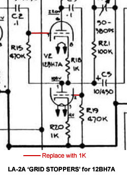
As you can see we need to add 2 x 1K resistors in series with the Pin 2 and 7.
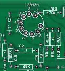
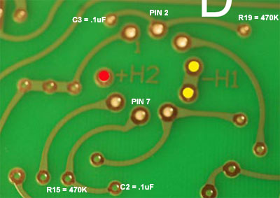
Looking at the Drip PCB here is what the silk side looks like.
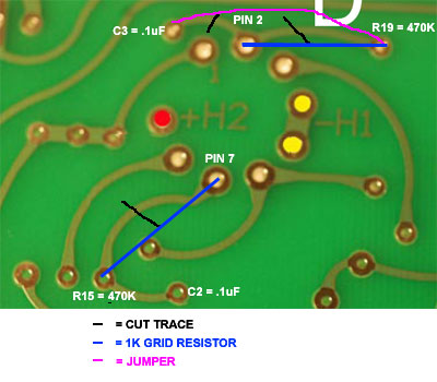
And the track side looks like.
Now I know what needs to be done but to be honest since I've not done this myself and I'm wondering what the easiest/cleanest way based the PCB above would be to do this 'mod'?
Cheers
Matt
Since this is being discussed at length and I know that parts of this info is scattered across various threads I thought I'd try put in all in one for future reference.
I'm sure there are quite a few people using the Drip Electronics LA-2A REV10 PCB for their LA-2A project, myself included, along with the Sowter Irons.
It was brought to my attention that this MAY cause oscillation and that 'grid stoppers' may need to be added and since these were not accounted for in the Drip Rev 10 boards, need to be added. (The newer boards have corrected this I belive).
Now what/how do we go about doing this, or where do they belong blah blah etc.
Quoting AnalogPackrat
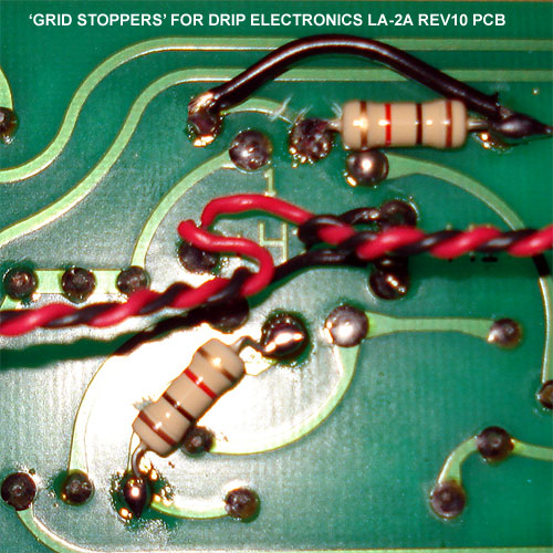
Are you using a Sowter output transformer? Those are known to sometimes cause HF oscillations in the WCF (12BH7 part of the circuit). To eliminate this, simply put 1k grid stopper resistors in series with the grids on both 12BH7 triodes. Desolder your current grid connections at the V2 socket, solder 1k resistors to the tube socket (pins 2 and 7) and then solder your original grid wires to the free ends of each 1k resistor.
Now this is easier said and done with a P2P version but how do we do with the REV10 PCB's?
Firstly lets look at the circuit diagram and see what needs to happen.
As you can see we need to add 2 x 1K resistors in series with the Pin 2 and 7.
Looking at the Drip PCB here is what the silk side looks like.
And the track side looks like.
Now I know what needs to be done but to be honest since I've not done this myself and I'm wondering what the easiest/cleanest way based the PCB above would be to do this 'mod'?
Cheers
Matt