GSSL HELP THREAD!!!

GroupDIY Audio Forum

Help Support GroupDIY Audio Forum:

This site may earn a commission from merchant affiliate links, including eBay, Amazon, and others.
Another thing I've just realized:
I don't have any voltage on the big cap 1000uF, the one closer to the 7915 and 7815.
On the other one I have around +23V on the positive side...
It could be the cap?
 
You are right Ruckus,
I'm sorry I'm a little confused...
I'll keep you updated if I have any other problems.
Another thing... I'm using That 2180A VCA, should I remove all these resistors as shown on the Matt Fischer page?
http://diy.fischerworks.com/gssl_vca.shtml

Thank you very much!
 
Here's a real dumb question for you guys, but I popped a capacitor when I first turned on the SSL so now I'm nervous!

The power switch I have lights up all the time when the power cord is plugged in, even when the switch is in the off position.  This isn't right, is it?
 
MikeFFG said:
Here's a real dumb question for you guys, but I popped a capacitor when I first turned on the SSL so now I'm nervous!

The power switch I have lights up all the time when the power cord is plugged in, even when the switch is in the off position.  This isn't right, is it?

No, it's not.  I don't know what type of power switch you have, is there an LED in it?  In any case if your light is on when your power switch is off then my guess would be you don't have your power switch wired correctly.
 
ya thanks I wanted to be absolutely sure it was wrong!  I have a typical rocker switch DPST.  I can't imagine how it could be wired wrong but I think I might have a transformer wiring problem...hmm.  I'll have to look into this more.
 
MikeFFG said:
ya thanks I wanted to be absolutely sure it was wrong!  I have a typical rocker switch DPST.  I can't imagine how it could be wired wrong but I think I might have a transformer wiring problem...hmm.  I'll have to look into this more.

Neither can I.  You only need to use one of the Poles, doesn't matter which, take your pick.  Hook your Line from the IEC connector to the "Common" of this Pole, Hook the Line from the Transformer to the "NO" of this Pole.  Or vica a vesa - doesn't matter, either way when you flip the switch it will complete the circuit.  It's as simple as that.
 
Alessio said:
You are right Ruckus,
I'm sorry I'm a little confused...
I'll keep you updated if I have any other problems.
Another thing... I'm using That 2180A VCA, should I remove all these resistors as shown on the Matt Fischer page?
http://diy.fischerworks.com/gssl_vca.shtml

Thank you very much!

Yes, follow the instructions on that page.  As far as you not getting Voltage on that CAP - I don't think you're putting your meter on the right pins.  The fact that you already told me you have +/-12V on your TL074 tells me you should have +/- voltage on your rails.  Put your meter across the 2 pins of the cap, blown or not, you'll still get voltage there.

Once again though, you still haven't given any sign or indications that you actually have a problem.
 
Just finnished my gssl with ssc mod! sounds great!
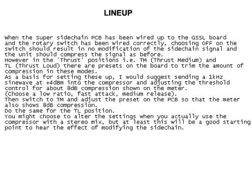
Is there any documentation about the trimpots on the SSC board? What is there  function and how do i need to set them right?

 
Pieter001 said:
Just finnished my gssl with ssc mod! sounds great!
Is there any documentation about the trimpots on the SSC board? What is there  function and how do i need to set them right?

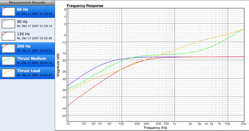
Yes, if you look in the ssc thread there's a link somewhere in there that's got a bunch of stuff.  Those trimpots calibrate the TM and TL settings.  Basically what those two settings do is boost high end and cut low end going into the sidechain so that the highs become uber-compressed and lows become under-compressed, giving the impression of a bass boost.  You can see on the graph that the TL setting is essentially a tilt eq.
Here's what they look like (90Hz and 130Hz settings are not shown on the graph):
filtercurves.gif
 
Hi everyone,
my GSSL works fine but I had a problem today. I was trying to power the LEDs for the switches (I've connected 2 switches for BYPASS and TURBO MODE instead of the rotary switches) and I've burnt the resistors on one side of the CRC (power filter) board.
I took the +15volts on the main PCB after the voltage regulators (where you could connect the SSC) for the positive of the LED with 1k resistor and the 0 volts from the main PCB (where there is the space for the transformer).
I've connected the first switch, I've tested it and everything was working so I've connected the second one and as soon as I've turned the unit on the resistors on the CRC started smoking... I've burnt them...
I've checked the connections 2 times and I cant find anything wrong... What happened? I'm sucking too much power? For 2 LEDS????

Any Ideas???

Thank you very much.
Alessio


I've probably understood what happened but I can't find a solution.
The first DPDT illuminated switch is the one for the TURBO mode and it works because I use 1 pole for the TURBO MODE and the 2nd pole for controlling the LED.
The second DPDT switch is for the BYPASS; here I use 1 pole for the BYPASS and the 2nd POLE to disable the GAIN. So I don't have anymore poles to control the LED. The first time I've connected the +15V together with the bypass pole and that makes the GSSL CRAZY and I've burnt the resistors on the CRC board!!!!!!

Is there a solution???
I could always use a rotary switch but the LED was nicer...

Please help!


Thank you,
Alessio
 
Thanks for the reply's! Used the gssl in a project today and discover a little hum (100 hz).
I have the inputs grounded to the chassis. Is this normal?
Its not that loud, but when i put it on my master track with some limiters behind it it get quite loud.

thanks for the help and this great diy project! :)
 
@Alessio: some possible options: 1) keep the makeup gain working by placing the wire link on control pcb instead to get a free pole for your LED switch, 2) switch the bypass and makeup by a dpdt relais, or 3) something like this scetchup.

@Pieter001: Check for ground loops. You might have more than 1 connection between 0V and case ground, such as metal/conducting standoffs for pcb mounting or used shielded wire with both shield ends connected. 100Hz sounds like post rectifier, so a CRC filterboard might improve this humming after fixing suspected ground loops.
 
have tried to disconect some groundpoints but the hum didn;t go away. I have the input grounded, the pcb grounded with the standoffs and the IEC.
I have already a supersidechain board connected to the main pcb. How many hum there is normally? Non?

 
Alessio said:
I will try the 3rd option... But with this option when the unit is in bypass is the gain disabled?
yes, but your meter will still display the amount of gain reduction that would be happening if not in bypass mode. The switch simply forces the audio VCAs into their bypass condition (control voltage=0V).
 
Mmm... I've tried that... it works... but I want the meter to go to 0 when the unit is in bypass.
So I was thinking if I connect the meter "+" connection (the one on the small pcb) through the switch on the same pole of the bypass and then come back to the pcb?
Is it something stupid?


Thanks a lot!
 
Pieter001 said:
have tried to disconect some groundpoints but the hum didn;t go away. I have the input grounded, the pcb grounded with the standoffs and the IEC.
I have already a supersidechain board connected to the main pcb. How many hum there is normally? Non?

There should be no hum at all.  If all your xlr connectors go straight to the chassis, then you should only use 1 of the 0V connections on the 5 terminal in/out spots.  If you have both of those 0V connections going to chassis, that's your ground loop.
 
Alessio said:
Mmm... I've tried that... it works... but I want the meter to go to 0 when the unit is in bypass.
So I was thinking if I connect the meter "+" connection (the one on the small pcb) through the switch on the same pole of the bypass and then come back to the pcb?
Is it something stupid?
It won't work this way, but thanks to the current limiting resistors inside the TL07x it probably won't smoke ;D . Three different potentials to switch. One pole for bypassing the variable DC voltage for makeup, next pole for the rectified/timed sidechain control voltage and a 3rd pole for your fixed voltage LED supply. Your DPDT switch only has 2 poles, so the easiest way might be a DPDT relais, controled by 1 pole of your switch, leaving the 2nd switch pole for your LED. There are other ways to control this, but these would require some more effort to make it work with same on-resistance, voltage swing and current drive ability.
 
Back
Top