GSSL HELP THREAD!!!

GroupDIY Audio Forum

Help Support GroupDIY Audio Forum:

This site may earn a commission from merchant affiliate links, including eBay, Amazon, and others.
Hi Jakob, thanks for the quick reply.
I understand that this is a characteristic of most compressors, I am more referring to the actual noise (clicks, pops) that the switch makes when changing it's value (higher or lower).

Thanks
 
Hi All,
        Haven t been in this thread in awhile.  getting back to my first GSSL , wanted to do the permanent Turbo with dual SSC's , I know there are a few graphics around showing this hook up arrangement , but am still stumped on the Dp8T  dual deck switch.  I know why its needed , but for me its actually getting the right switch , I can only seem to find 10 or 12 position switch, and so far not knowing how to get it to stop at the 8th position ( or to just deal with it ) has given me an Idea  ( watch out .. the smoke is rising )  ;D   

    can the EXT (s/c )  and the OFF positions from the SSC be hooked up to a DP3T  ON-OFF-ON switch ?    - and then use a 2 X 6 Lorlin for the remaining ? 

  and if so .... how would that be wired ? 

  Thanks,
            Chip
 
audiophreak said:
Hi All,
        Haven t been in this thread in awhile.  getting back to my first GSSL , wanted to do the permanent Turbo with dual SSC's , I know there are a few graphics around showing this hook up arrangement , but am still stumped on the Dp8T  dual deck switch.  I know why its needed , but for me its actually getting the right switch , I can only seem to find 10 or 12 position switch, and so far not knowing how to get it to stop at the 8th position ( or to just deal with it ) has given me an Idea  ( watch out .. the smoke is rising )  ;D   

    can the EXT (s/c )  and the OFF positions from the SSC be hooked up to a DP3T  ON-OFF-ON switch ?    - and then use a 2 X 6 Lorlin for the remaining ? 

  and if so .... how would that be wired ? 

  Thanks,
            Chip
Don't think so. Why not ditch the external sidechain option (how often are you going to use it?) and one of the lesser used SSC filter frequencies and just use a Lorlin 2 x 6? I have 2 dual SSC / Turbo GSSL's. I bought 2x12 switches but they're pretty clunky in use, and I remember a discussion on the thread that no-one had managed to find a dual-deck 12 way switch with a nice action for a reasonable price.
 
MeToo2 said:
audiophreak said:
Hi All,
        Haven t been in this thread in awhile.  getting back to my first GSSL , wanted to do the permanent Turbo with dual SSC's , I know there are a few graphics around showing this hook up arrangement , but am still stumped on the Dp8T  dual deck switch.  I know why its needed , but for me its actually getting the right switch , I can only seem to find 10 or 12 position switch, and so far not knowing how to get it to stop at the 8th position ( or to just deal with it ) has given me an Idea  ( watch out .. the smoke is rising )  ;D   

    can the EXT (s/c )  and the OFF positions from the SSC be hooked up to a DP3T  ON-OFF-ON switch ?    - and then use a 2 X 6 Lorlin for the remaining ? 

  and if so .... how would that be wired ? 

  Thanks,
            Chip
Don't think so. Why not ditch the external sidechain option (how often are you going to use it?) and one of the lesser used SSC filter frequencies and just use a Lorlin 2 x 6? I have 2 dual SSC / Turbo GSSL's. I bought 2x12 switches but they're pretty clunky in use, and I remember a discussion on the thread that no-one had managed to find a dual-deck 12 way switch with a nice action for a reasonable price.

  Thanks ... I kinda thought so, but wanted to ask.  The switches mentioned  do look " Clunky " and not sure they would fit in a 1U Par case.  I was thinking about dropping the external S/C  too - dont think I'd ever use it - but wanted to keep everything else which still left me out with the 2 x 6 Lorlin.  Still gonna look for options , if I find something I will post back.... I'm sure I'll have more questions  ;D
 
audiophreak said:
  Thanks ... I kinda thought so, but wanted to ask.  The switches mentioned  do look " Clunky " and not sure they would fit in a 1U Par case.  I was thinking about dropping the external S/C  too - dont think I'd ever use it - but wanted to keep everything else which still left me out with the 2 x 6 Lorlin.  Still gonna look for options , if I find something I will post back.... I'm sure I'll have more questions  ;D
FYI The Electroswitch C4D0212N-A 2 deck switches did fit in a Parusha 1u case no problem. They work OK, but they do require quite a high turning torque, which is a clear disadvantage compared to the Lorlins.
 
Hey Guy's, Nearly finished my build... BUT does any one in the the UK have a transformer they can reccomend?
Cheers!
.... would this one do?
http://uk.farnell.com/multicomp/mcfe015-15/transformer-15va-2-x-15v/dp/9531670
 
Hi ppl,

I finished my GSSL w / ssc :)))). It is working but seems to have something wrong
As soon as I turn on the "compressor in" with the treshold = +20, ratio = 2, =. 1ms Attack, Release and SSC = 1 = off. the meter is to-15dBm. When I insert the audio meter slope after -20. This is normal?

The variation of the treshold should get affected?


Thanks
Hugo 
 
greyskull said:
Hey Guy's, Nearly finished my build... BUT does any one in the the UK have a transformer they can reccomend?
Cheers!
.... would this one do?
http://uk.farnell.com/multicomp/mcfe015-15/transformer-15va-2-x-15v/dp/9531670

I am using this exact transformer at the moment, works great.
 
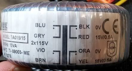
Hey guys, I'm having some trouble connecting my transformer. I've connected it as follows:

Brown wire to AC active
Violet wire to Grey wire
Blue wire to AC neutral

Yellow wire to the top pin (of the three AC in connectors in this pdf http://www.gyraf.dk/gy_pd/ssl/ssl.pdf)
Red and Orange wire to the centre pin
Black wire to the bottom pin

When I connect the power and fire it up, voltages seem a little high (reading 18V) when it's disconnected from the PCB although as soon as I connect it, the bottom pin is giving me 0V and the top pin is giving 12V. It also gets very hot and hums quite loudly when connected to the PCB.

I'm pretty sure I've connected it wrong, can someone help me out? Below is a photo of the trafo.

Trafo.jpg

 
OKay.. sorry guy's just one more thing to add to this order.....
Instead of using the lorling style switch for power, I'd prefer to use a toggle, the big chunky kind... and the same for bypass and turbo/gyraf operation.... what ratings etc would i need for these?
 
Enchilada,
this is not really gssl specific. your primary side wiring will obviously depend on what mains voltage you are plugging into. you have wired it for 230v but your location is not visible.

unloaded supplies will often be higher.

the brown and blue have always been 'live' and neutral respectively.

EDIT:

the live brown bear sits on the green earth under a neutral blue sky.
At least the bears in the UK do :)
 
Enchilada,
you already cleaned the pcb surface from the conducting liquid from your blown 1000uF cap?,
you used a magnifying glass to inspect and remove possible shorts between pcb traces from your home etched board,
assuming at least one short behind the bridge rectifier, this little rectifier will probably be blown from current demand, exceeding parts limits.
As previously mentioned, please update your profile with your location info. This is an intercontinental forum and not only mains voltages are different.
 
@ Kepeb,

I'm In Australia so yes, I'm wiring for 230V. I would say this is GSSL specific because voltages appear to be fine straight from the trafo but as soon as I connect the trafo to the PCB, there is an audible hum from the trafo and voltages change to around 11V on the yellow wire and just over 0V on the Black wire. BTW, thanks for the handy saying  ;).
@Harpo

I was testing voltages with the PCB upside down so no liquid came into contact with the PCB. I went over the PCB with a magnifying glass lamp combo that I have prior to populating it and I cut the few shorts I did find with a scalpel. I will double check that though. If there were any shorts, they would be after the bridge rectifier. Pretty sure there aren't any though.

What else could be causing the voltage readings to change at the pins? I assumed I must have connected the trafo to the PCB incorrectly.

EDIT: I've updated my profile to reflect my location.

EDIT 2: Just double checked under 8x magnification and there are definitely no shorts on my PCB.
 
hey, yea - I was referring to the primary side wiring when saying non specific.. as in, it applies to all mains wiring where you are.

but for the gssl side I would usually check all the IC's first if the voltage is pulled down at the board, there must be a short/wrong resistor or the reg has gone.

what are the voltages at the regulator outputs?
where you are measuring, the 'pins'... you mean this is where your traffo connects to the board?
 
I haven't put in any of the ICs yet, I wanted to check the voltages first in case I fried one if them. I'll check voltages at the sockets and the regulator outputs tomorrow. And yes, by pins I mean where the trafo connects to the board. I checked every resistor with my multi before soldering so that's not the issue.

Has anyone else had their trafo humming? By that I don't mean on the output. There's actually an audible hum coming from the trafo itself when it's connected to the PCB (no hum when it's not connected to the PCB).

Kris
 
Did you check for short between pcb power rails and ground, without the transformer connected and probing the rails with digital voltmeter set to ohm or continuity buzzer mode ?

 
keefaz said:
Did you check for short between pcb power rails and ground, without the transformer connected and probing the rails with digital voltmeter set to ohm or continuity buzzer mode?

I'll give this a go and see what I come up with.
 
Had a go at checking for a short between the PCB power rails and ground. Wasn't 100% sure I was doing it right but I don't think there is a short.

I went over the PCB again with magnifying glass to make double sure I couldn't see any shorts and found nothing. I also replaced the bridge rectifier and the blown cap (this time with the correct polarity). Still got the hum and incorrect voltages at the pins. There are two points on the PCB labelled +15V and -15V, these are testing as 0V with my multimeter. Should these not read +-15V without the ICs?

One thing I tried just for fun was to plug the centre and the bottom pin on their own. When I did that it read 18V and there was no hum from the trafo. Next I plugged only the centre and the top pin and the hum returned. Hopefully this can help narrow it down.

Here's a pic of my PCB, can anyone spot any possible simple mistakes?
http://i1188.photobucket.com/albums/z413/Krisbo_ench/GSSL/20111026_185143.jpg
 
Enchilada said:
Here's a pic of my PCB, can anyone spot any possible simple mistakes?

Hi, just had a quick look at it.At a first sight I´ve noticed you mounted 2 rectifiers-the left in your pic is not needed (only for on-board transformer).

Maybe will find more when time permitting...

..and have a good look that the metal sides of the regs don´t touch each other...I remember that they where mounted pretty close to each other...

Udo.

Edit:Found this in my archive from my first build-a test points layout for the pcb without any ics or vcas plugged in-good trouble shooter (see att.file):
 

Attachments

  • GSSL voltage test points.pdf
    294.5 KB

Latest posts

Back
Top