GSSL HELP THREAD!!!

GroupDIY Audio Forum

Help Support GroupDIY Audio Forum:

This site may earn a commission from merchant affiliate links, including eBay, Amazon, and others.
2) off board ±15V regulated supply based on LM317/LM337 for powering the GSSL main board + dual SSC filter boards + VU driver board.
I had this PSU board left over from a dual MNATS 1176 build

damn, that is a top idea, stupid that i didn't think of that before, i ALSO have one left from mnats' 1176 lol

so i shouldn't have ordered a special lm317/lm337 pcb from ebay after all...

i am excited! i'll try this afternoon :D

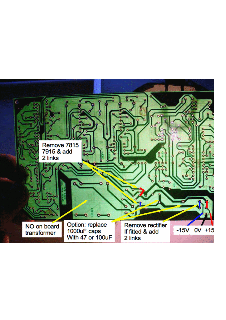
But how do i use it? do i take the power from my toroid directly onto mnats' board, and where do i connect the 15- and 15+ then coming off that board? Do i have to remove components from the main board then? (like the 1000uf caps, VR's etc?) which ones?

 
Anyway you want to measure all 4 rails to identify the fault.
If the +/-12V regulators are hanging on startup (IE your LED is powered by the +12V rail), a corresponding fix for the 78L12/79L12 as described for the 7815/7915 anti-latchup might do it.
A separate 317/337 psu for the +/-15V probably won't fix the maybe hanging 78L12/79L12.
A faulty mains switch will not get fixed by a seperate psu as well.
 
But how do i use it? do i take the power from my toroid directly onto mnats' board, and where do i connect the 15- and 15+ then coming off that board? Do i have to remove components from the main board then? (like the 1000uf caps, VR's etc?) which ones?
 
synnys said:
But how do i use it? do i take the power from my toroid directly onto mnats' board, and where do i connect the 15- and 15+ then coming off that board? Do i have to remove components from the main board then? (like the 1000uf caps, VR's etc?) which ones?
Firstly, temper your excitement and read what Harpo has written..... Check where your current fault lies before you go butchering your board. Latching 12V will not be fixed by an external 15V supply. Having said that I prefer an external supply as the LM317 has better regulation in the AF band than a 7815.

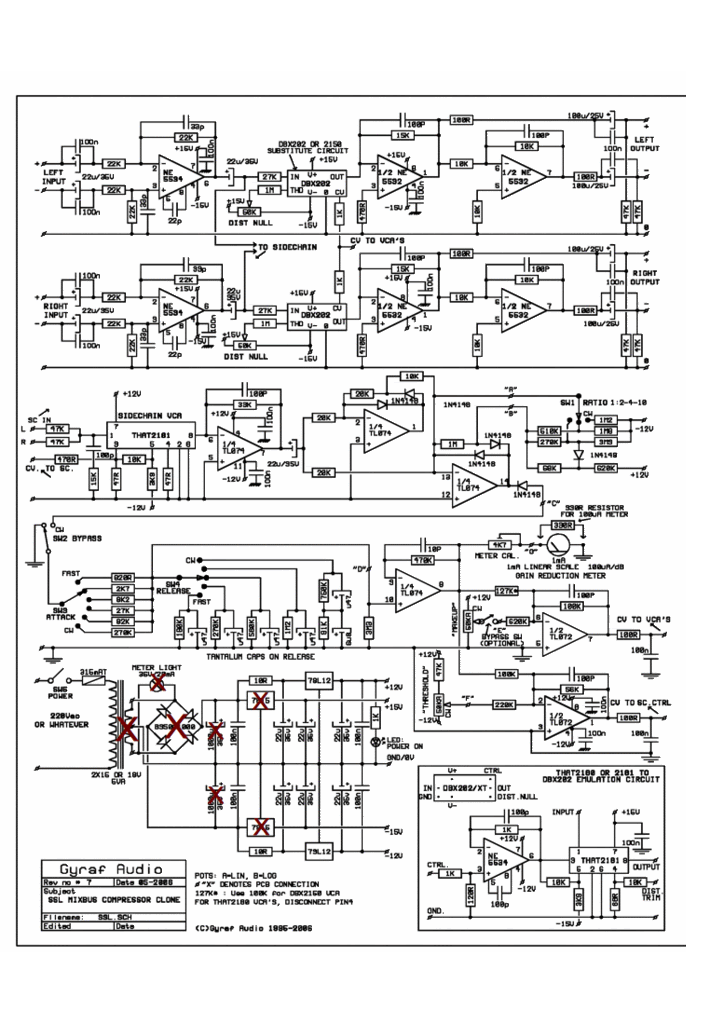
Here's how I hooked mine up, and what mods I made:

ssl_sch3a.gif

pcb3a.gif
 
thanks very much for sharing  that, that really helps a lot.

and as far as for what harpo said, it is indeed my 12v rail that is hanging. (IE on faulty boot, my power led won't light up) but i tried using the 100nf caps and the extra diodes on the other side of the pcb and that didn't do anything for me.

And i'm indeed using an external 2x15v toroid psu.

i'll let you know how it goes...

... off to the soldering iron :D
 
synnys said:
thanks very much for sharing  that, that really helps a lot.

and as far as for what harpo said, it is indeed my 12v rail that is hanging. (IE on faulty boot, my power led won't light up)
You could also try increasing the resistor on the power LED by 15/12 and powering the LED from the ±15V supply.
The 7812 and 7912 ±12V rails are meant to be quiet, so I wouldn't go hanging any unnecessary stuff off them.
 
ok so i removed the components, hooked up the mnats psu thingy, and the problem remains... sigh.

How do i measure the 4 rails?

is it multi meter black on the ground and red on the 15+/15- for measuring my 15v rails,
and multi meter black on the ground and red on the 12+/12- (on the control pcb the -/+ pins?) for measuring my 12v rails?

oh and btw, you asked earlier what mods i have, i only have the super sidechain
.
 
So my measurements:

after good boot: 15v/12v are ok, unit is working good.
after faulty boot: 15v +/- are ok.

12v on the other hand are not, i measure -12v and -0.8v, that's probably also why my power led doesn't light up, because the voltage there is also -0.8v.

Also, after a faulty boot, my panelmeter (the one from hairball) goes up to 2dB where as with a normal boot it would be at 0 dB.
and when i power off after a faulty boot, my power led flashes once before the unit goes out, must be a cap decharging i guess?
Can i conclude that my 78L12 is making all the troubles for me and not the 7815/7915 VR's?

So on to the led-off-the-12v-rail suggestion. would it make a difference if i just replaced the 1k before the led with a 2k for instance?
or would you recommend just disconnecting it all together from the 12v?
 
synnys said:
So my measurements:

after good boot: 15v/12v are ok, unit is working good.
after faulty boot: 15v +/- are ok.

12v on the other hand are not, i measure -12v and -0.8v, that's probably also why my power led doesn't light up, because the voltage there is also -0.8v.

Also, after a faulty boot, my panelmeter (the one from hairball) goes up to 2dB where as with a normal boot it would be at 0 dB.
and when i power off after a faulty boot, my power led flashes once before the unit goes out, must be a cap decharging i guess?
Can i conclude that my 78L12 is making all the troubles for me and not the 7815/7915 VR's?

Yes, certainly looks that way. The panel meter reading is probably a symptom of the TL074 not getting +12V rather than the root cause.

So on to the led-off-the-12v-rail suggestion. would it make a difference if i just replaced the 1k before the led with a 2k for instance?
or would you recommend just disconnecting it all together from the 12v?
Worth a try as it will reduce current. You could also just try disconnecting it temporarily to see if it the fault is associated with the power LED. And maybe also check for dry solder joints on the 7812.

Is your SSC board powered from ±15V (as that contains quite a chunky relay)?
 
synnys said:
..but i tried using the 100nf caps and the extra diodes on the other side of the pcb and that didn't do anything for me...
Just added the diodes for the +/-12V regulators to previous anti-latchup fix. Maybe reload the pic.
The 100nF caps in front of the 7815/7915 are already shown in the schematic, but are in front of the 78L12/79L12 on pcb instead.

Did you already try a different brand of 78L12/79L12 regulators ?
 
[quote author=MeToo2]You could also try increasing the resistor on the power LED by 15/12 and powering the LED from the ±15V supply.
The 7812 and 7912 ±12V rails are meant to be quiet, so I wouldn't go hanging any unnecessary stuff off them.
[/quote]

i could kiss you, just so you know... that did the trick!

I disconnected the led from the control pcb and connected it to ssc led IN. so now the led only lights up when the unit is not bypassed, but that works for me.

Who would have thought that all this time this problem was caused by a little LED?! pffff...

I'm happy :D Thanks a lot metoo2/harpo for all your thoughts.


Which brings me to my other problems ;)

- My make-up gain only does about 15dB, how can i get it up to 20dB (cause i engraved that on my frontpanel, would be nice if that would correspond...)

- I noticed that the threshold values change when switching ratios, while that isn't really my issue, the values of the gainreduction meter are way off when switching ratio's  so i can't really rely on those readings... I replaced the 1k meter sensitivity with a 5k multiturn trimpot so i could fine-tune the meter, and while this works perfect, the values are still off when switching ratio's... Can this be fixed? or is this just a designflaw maybe?
 
hmm disregard my last post, i was happy too quick. Problem is still there, only before i moved the led, the led was actually my indication if the unit latched-up or not, and as my 15v rails is working fine, it's no wonder my led now lights up at every boot lol,

now at a faulty boot the meter goes all the way up to 8dB, whereas it was about 2dB with the led attached to the contorl pcb, must be the difference in current drawing causing that...

Anyway, harpo, i'll try the diodes at the 7812/7912 location you drew on the refreshed picture. thanks for that!

And to answer your question, no i haven't changed 7812/7912 brands as i thought my problem was caused on the 15v rails.. will buy some tomorrow just in case...
 
Harpo said:
Just added the diodes for the +/-12V regulators to previous anti-latchup fix. Maybe reload the pic.
The 100nF caps in front of the 7815/7915 are already shown in the schematic, but are in front of the 78L12/79L12 on pcb instead.

Actually THIS did the trick harpo! Thanks so much. I tried cold-booting it at least 20 times now, never failed...!

T  H  A  N  K      Y  O  U !

So now the next problems on my list ;)
 
Mi unit tracks stereo perfectly, I went with a 24K in series with a 2K trimmer in a little piece of perforated board. Thanks for the tip Harpo.

Now I'll work on the failure when turning the unit on, I'll post back soon, thanks!
 
synnys said:
- My make-up gain only does about 15dB, how can i get it up to 20dB (cause i engraved that on my frontpanel, would be nice if that would correspond...)
..about 17.15dB. Anyway 5dB more wanted ? decrease the 620K to 480K. A 470K would be a standard parts value for a 5.47dB increase.
 
Harpo said:
synnys said:
- My make-up gain only does about 15dB, how can i get it up to 20dB (cause i engraved that on my frontpanel, would be nice if that would correspond...)
..about 17.15dB. Anyway 5dB more wanted ? decrease the 620K to 480K. A 470K would be a standard parts value for a 5.47dB increase.

Top! will try it, thanks.

edit:

well fast as i am, that actually didnt make any difference in make-up gain for me....? I replaced 620k with a 470k... still about 15dB
 
synnys said:
well fast as i am, that actually didnt make any difference in make-up gain for me....? I replaced 620k with a 470k... still about 15dB
dB what ? What is your signal feed level in VRMS at GSSL input ? You might be feeding the GSSL from a converter with your DAW showing maybe 0 dBfs. Your converter might be calibrated to put out 0VU=+4dBU=1.223VRMS somewhere in range between -14 .. -20dBfs. 1.223 VRMS*SQRT(2)=1.73Vpk. Boosting this level by +15dB is a voltage gain of 5.62; by +20dB is a voltage gain of 10. 1.73Vpk*10 would be 17.3Vpk where your NE5532 on GSSL out could only swing to about 13Vpk with its +/-15V supply.
 
Harpo said:
synnys said:
well fast as i am, that actually didnt make any difference in make-up gain for me....? I replaced 620k with a 470k... still about 15dB
dB what ? What is your signal feed level in VRMS at GSSL input ? You might be feeding the GSSL from a converter with your DAW showing maybe 0 dBfs. Your converter might be calibrated to put out 0VU=+4dBU=1.223VRMS somewhere in range between -14 .. -20dBfs. 1.223 VRMS*SQRT(2)=1.73Vpk. Boosting this level by +15dB is a voltage gain of 5.62; by +20dB is a voltage gain of 10. 1.73Vpk*10 would be 17.3Vpk where your NE5532 on GSSL out could only swing to about 13Vpk with its +/-15V supply.

I use a motu 828mk3 which has an fft analyser. in my daw i generate a 1kHz sinewave at 0dB, that goes thru the compressor and comes back into the audio interface at 0dB.
When i now reduce the gain with compression for instance by about 20 dB, and the put make-up gain to the maximum, it only boosts the signal by about 15.5 dB leaving my signal at -4.6dB or something... and that was the same before is changed the 620k to 470k

gonna do some more testing today and will try to understand your math... ;)
 
Hi,

I did a prinzipal schematic how I checked my U373 and made a new meter scale for it.
Maybe this would help you!?
http://www.groupdiy.com/index.php?action=dlattach;topic=11121.0;attach=14288;image

ROCK-ON!
 
Back
Top