GSSL HELP THREAD!!!

GroupDIY Audio Forum

Help Support GroupDIY Audio Forum:

This site may earn a commission from merchant affiliate links, including eBay, Amazon, and others.
Harpo said:
decrease the 620K to 480K. A 470K would be a standard parts value for a 5.47dB increase.

you were right ofcourse, i changed to 620k on the control pcb to 470k instead of the one on the main-board, silly me :D

Works fine now, thanks!
 
So how about ratio calibration? I know i can replace the 127k with a 200k trim for calibration, but i don't quite understand how to measure it?
Does someone care to elaborate?
 
synnys said:
It's an FAQ. Look back in the thread a few pages. Slope = delta output / delta input. But don't measure near the knee: the unit has to already be compressing somewhat to measure the ratio properly. Yes the knee / threshold is at a different level for each setting of the ratio switch. The GSSL uses logarithmic VCA's. So the control voltage is proportional to the dB reduction/ gain + an offset. Changing the 127K will change all ratios by the same amount. If you want to tune each ratio separately you need to be looking at the resistors around the ratio switch. My unit was bang on without any further tuning, so no it's not a design fault.
 
Hi,
I just finished my first GSSL, rev#7 board. I got only 1 channel working.
The other one is really really low volume.
PSU voltages are all ok. IC's orientations are ok. I use THAT2180LB
I checked voltages on outputs +/-, putting a 1KHz square wave on both imputs at +4dB (1,5Vac on positive input).
One output seems ok, same voltage on + and - pin (about 0,750Vac measured with a multimeter and an oscilloscope too)
The other output gets ≈0,7Vac on positive output and ≈13Vac (yes...13Vac) on negative output.

I tried to swap the 2 VCA's with no change at all.
So i think it's about one output stage. I noticed that on schematic the output signal from VCAs should go on Pin 2 of NE5532s, but it goes on pin 6 instead. Seems that the two internal opamps are used inverted from schematic. And should be fine, if also the resistors are swapped. On this, I noticed something strange. By schematic:

between pin 3 and ground I should read 470Ω
between pin 5 and ground I should read 10kΩ

In my circuit i read 470Ω in each location, for each NE5532.


Can someone help me?
thanks!
 
qwerty8787 said:
...The other output gets ≈0,7Vac on positive output and ≈13Vac (yes...13Vac) on negative output.
so the fault is at the last stage inverting unity gain buffer.
Double check the value of last stage input resistors (10k between pins 7/2 on pcb, between pins 1/6 on schematic) or more likeley remove the short at the 10k resistor leg close to the left side bal.output +/- connection. (Using a magnifying glas might help to spot the short.

So i think it's about one output stage. I noticed that on schematic the output signal from VCAs should go on Pin 2 of NE5532s, but it goes on pin 6 instead.
Stages of this NE5532 dual opamp are swapped. No big deal. There are some more differences between schematic and pcb revisions.
 
yeah, there was a short between two legs. now the output voltages are correct! i'm gonna put some audio through it right now.

three more questions:

1 - TL/TM calibration:

searching tru the forum I found your explanation for making this calibration. I have a question: I found months ago a picture showing frequency response of the 8 SC filters. Keeping in mind that, shouldn't be correct making your calibration procedure with a testing frequency tone of about 400-500 Hz instead of 1KHz? In this frequency range the figures are closer to each other, so they respond the same way, instead of 1Khz where the TL curve gets about 5dB farther.
Is my thought wrong?

2 - Crazy Ratio

at 2 i get more compression (on meter) than at 4. Same thing by 4 to 10. I read somewhere that this is regular but I'm afraid that I could have made some mistakes. I putted the ratio rotary switch direct on his pcb. I still have to put stopping dents on it (I lost them, I have to replace them in some way) but if I star with the know fully counterclockwise I should be on 2, then clockwise for no more than 2 clicks. Is this operation correct?

3 - Bypass

I thought that bypassing would simply exclude the VCA's leaving them operate, so I expected the meter to move with unit bypassed. Are there any mods or improvements for bypass?


Thank you so much for your help!  ;D

 
Can anyone out there tell me where I'm supposed to run the output from the crc board? I don't have any of the other mods but I noticed that everyone who does any mod runs them into the corner by the large caps. Yes, I am new at this.
 
I hooked  up the crc from the  way it looks from the expat site (the way I've done most of my DIY work) and now it won't power on at all.  Any ideas? Soldering looks good and everything worked fine just before I put this thing in, no smoke, fuse is good, just nothing.
 
psyche,

This is the help thread for the basic-version GSSL (which is the only version I have built) - I'm pretty sure that there are dedicated help threads around for the add-ons.

Jakob E.
 
I feel this is a very strange problem...

I have a protools session setup so I can Bypass the signal generator going into my GSSL. When I switch back and forth, that is turn the Signal Generator on and off... I get different compression amounts??? Sometimes it might be 5db... then I click the bypass button again a few times (signal generator) and it now compresses 10db, then 2, then kinda all over... it always seems to go back and forth between 2 or 3 different amounts... instead of say like 50 different levels...

Any ideas???
 
Harpo said:
Aniol1349 said:
..question deleted..
-> answer deleted.
good luck

sorry Harpo, but the switch I was asking for was wrong as I realized, so I deleted the question.


I'm getting really frustrated because I got this lovely case from Pursha and I can't find pots for 9mm mouting hole,
could any one help me to find those pots?

Also, when I'm grounding my gssl do I take all the pins 1 from inputs and outputs xlr's and wire them together into a star ground? Does the 0 from the in and out terminals go there as well? Making balanced in's and out's confuses me a wee bit, and there's not really that much info on this.

Does the grounding from the power socket go together with the audio grounding? or should it be away from it?

I'm gonna use the SSC board, do I need to ground anything there?

am I missing still something?

Hope someone could answer me on those?

Thanks
 
I've finally almost completed my gssl.

After doing calibration, i noticed that the output is 1dB higher than input, even in bypass (with make-up gain switched out)

Then, the threshold pot isn't in the exact range. If i feed the compressor with a 1kHz 0dBu signal (0.775VAC measured with multimeter), the threshold should be turned down to around -4 before the compression knocks in (with 10:1 ratio). I guess it should knock in at 0, so at potentiometer middle position. It's a bit disappointing because I've marked the panel scale with -15, 0 and +15...

What do you think? There is something I can adjust?

 
Hi

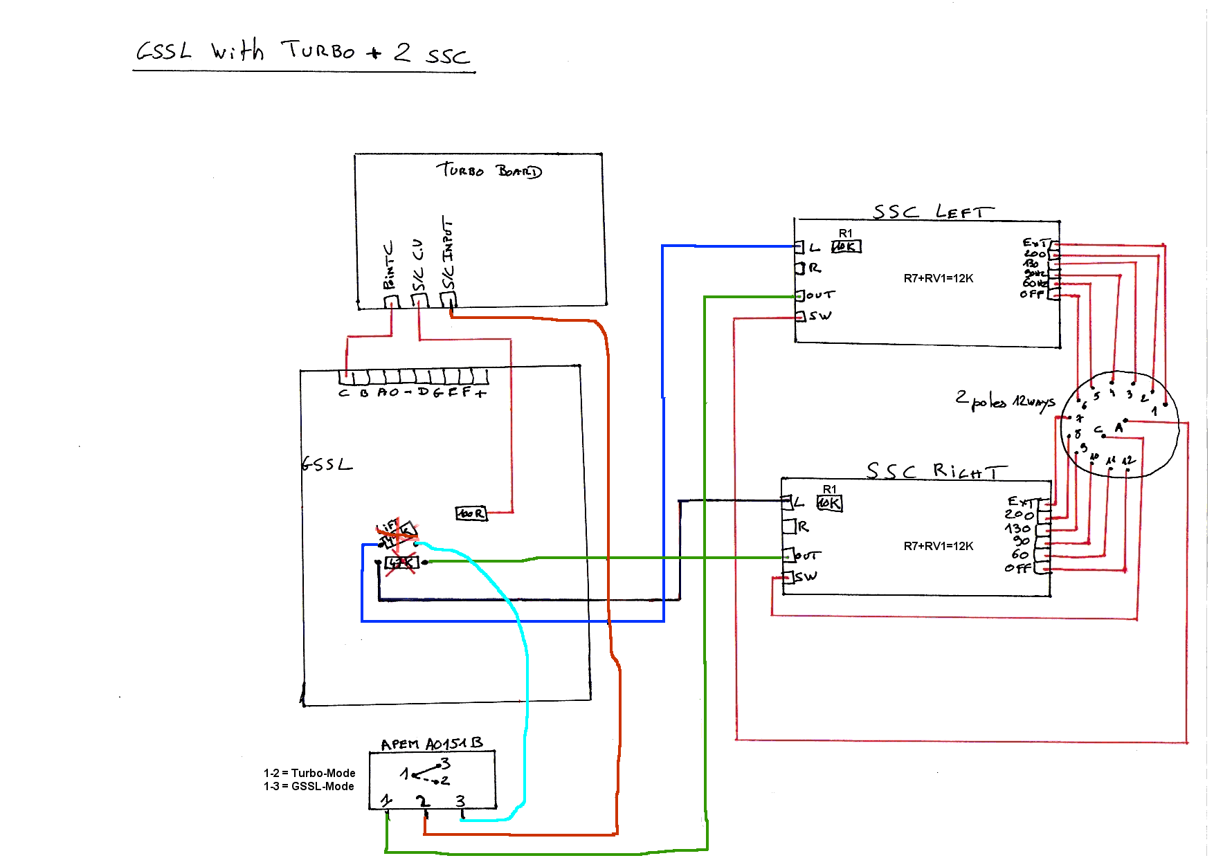
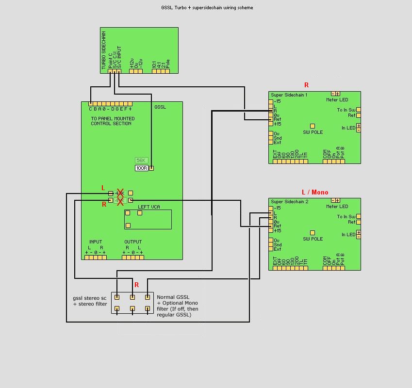
I'm building a GSSL + 2SSC + Turbo, but I'm little confused...
- In the IN/OUT section on the SSC board (Com, On, Off, Pot A, Pot B) should be soldered on the GSSL's Control Board. Should I keep the bypass rotary switch ?
- Is the Off position of the SSC for bypassing the GSSL or only the SSC ?
- So, what is for the In switch on the SSC ?
- Must I link the IN/OUT section to the second SSC board ?
- Wich wiring is correct ?

GSSL_Turbo_DualSCF.gif

or
GSSL_turbo_ssc_edit.jpg


I can't find the answers in the GSSL threads...

Thanx a lot
 
shredup said:
I can't find the answers in the GSSL threads...
Maybe because these questions are not GSSL but SCF related ... ;)
Lots of ways to shave a cat, but why would you expect two different sidechainfilter boards (and these are not the only ones) in a different context being wired the same way ?
 
Hi guys,

I'm quite sure my GSSL is not compressing correctly, because no matter how loud my input signal is, and with the threshold position at 100% CCW, the output signal will always be 1dB-3dB down for 2:1 ratio, 3dB-4dB down for 4:1 ratio, and 4dB-6dB down for 10:1 ratio.

Playing around with the timing controls only varies the gain reduction by 0.5dB to 1dB, for an example, if at 2:1 ratio 0.1ms attack 0.1s release i get 2dB gain reduction, switching to 1ms attack, i may get 1dB gain reduction or no gain reduction at all.

Compression also only kicks in when the threshold is turned to 95% to 100% CCW (when negative DC voltage appears on TL072 pin 1). If I mounted the 47K resistor to reduce the sensitivity, at 100% CCW, I got no compression.

Some DC voltage measurements:
Supply rails -15.47V / 15.43V, -12.24V / 12.25V

TL072 pin 1, threshold CCW -3V, threshold CW +3V (unaffected by other controls)

TL072 pin 7, makeup CCW -1.90V, makeup CW 0V

Can't test for AC voltages, because my DMM don't read down to mVAC.

Traced for continuity and didn't find a short circuit.
Checked for cold solder joints, and found none.
Replaced the TL072, TL074, THAT2180, and I still get the same result.
Checked for lousy capacitors, and found none.
Resistor values are also correct.

Another problem is the auto release (2.4s) timing. It distorts the output signal.

Weird thing is, regardless of these problems, the compressed audio still sounds great. When I played around with the controls (leaving threshold at 100% CCW, and ignoring auto release), then comparing with the audio in bypass mode, I definitely heard the differences.

Help!!!!  :'(
 
I'm quite sure my GSSL is not compressing correctly, because no matter how loud my input signal is, and with the threshold position at 100% CCW, the output signal will always be 1dB-3dB down for 2:1 ratio, 3dB-4dB down for 4:1 ratio, and 4dB-6dB down for 10:1 ratio.

Playing around with the timing controls only varies the gain reduction by 0.5dB to 1dB, for an example, if at 2:1 ratio 0.1ms attack 0.1s release i get 2dB gain reduction, switching to 1ms attack, i may get 1dB gain reduction or no gain reduction at all.

Why would you expect compression to change significantly with timing?

Compression also only kicks in when the threshold is turned to 95% to 100% CCW

At what analogue input level? The comp is designed for levels around +4dB over 775mV ac

Another problem is the auto release (2.4s) timing. It distorts the output signal.
Check that you have both timing caps in place for auto (0u47 and 6u8)

in haste,

Jakob E.
 

Latest posts

Back
Top