spudstyle
Well-known member
- Joined
- Jun 5, 2012
- Messages
- 57
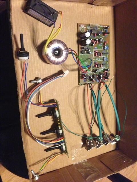
Harpo said:Your 100pF cap is OK. You won't find a cap with this dialectric where voltage rating in this spot will be your concern.spudstyle said:Ok, now my compressor is working but on my left channel, I got a ground noise. The right channel is ok, very low noise. My kit is from PCBGrinder and a capacitor was missing in the package (cause the BOM say 9x100pf and really need 10). I find another capacitor at home that is 100pf but not the same size cause it's a 500v (see attached picture). So this capacitor can be the problem ? In this case, what type of capacitor I need ? 50v, 100v ? I don't have the reference of PCBgrinder kit capacitor.
Thanks for your help.
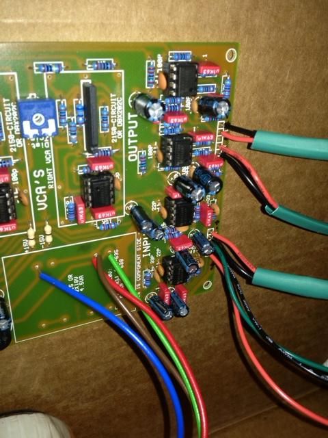
Some other parts in the blurry area of your pic are at least questionable, IE without trimmer fitted, ment for a different type of VCA, some resistors are one side connected only, doing nothing. The pretrimmed THAT2180 VCAs prefer pin4 unconnected, so you might pull out the 47R and 68Rs connecting to THAT2180 pin4. Other members snipped pin 4 off or bent this pin sideways, so it didn't make connection to pcb (just leaving the 47R or 68R out seems easier/cheaper, but YMMV). You might pull out the 10Ks between VCA pins3/5 as well, once ment for a different type of VCA.
Whatever your 'noise' might be, this will more likely be either hum at double mains frequency, caused by ground loop(s), hum at mains frequency, induced by your mains transformer or hiss, caused by a missing ground connection. From your pic, seeing the molex center pin connected, this might be caused by the 1st case. XLRs pin1 connect to chassis in the shortest possible way and using seperate wires instead of a mic cable (with shield only one side connected), you want the wires connecting between XLR-pin2/3 and pcb twisted together, so the differential receiver has a better chance to cancel out induced garbage. Using metal/conducting standoffs in the wrong spot might be another reason.
Just my 2ct.
Thank you very much ! I will remove 47k, 68R and 10k.
For the noise, I will follow your advices. Thanks


![Soldering Iron Kit, 120W LED Digital Advanced Solder Iron Soldering Gun kit, 110V Welding Tools, Smart Temperature Control [356℉-932℉], Extra 5pcs Tips, Auto Sleep, Temp Calibration, Orange](https://m.media-amazon.com/images/I/51sFKu9SdeL._SL500_.jpg)


")