Greg
Well-known member
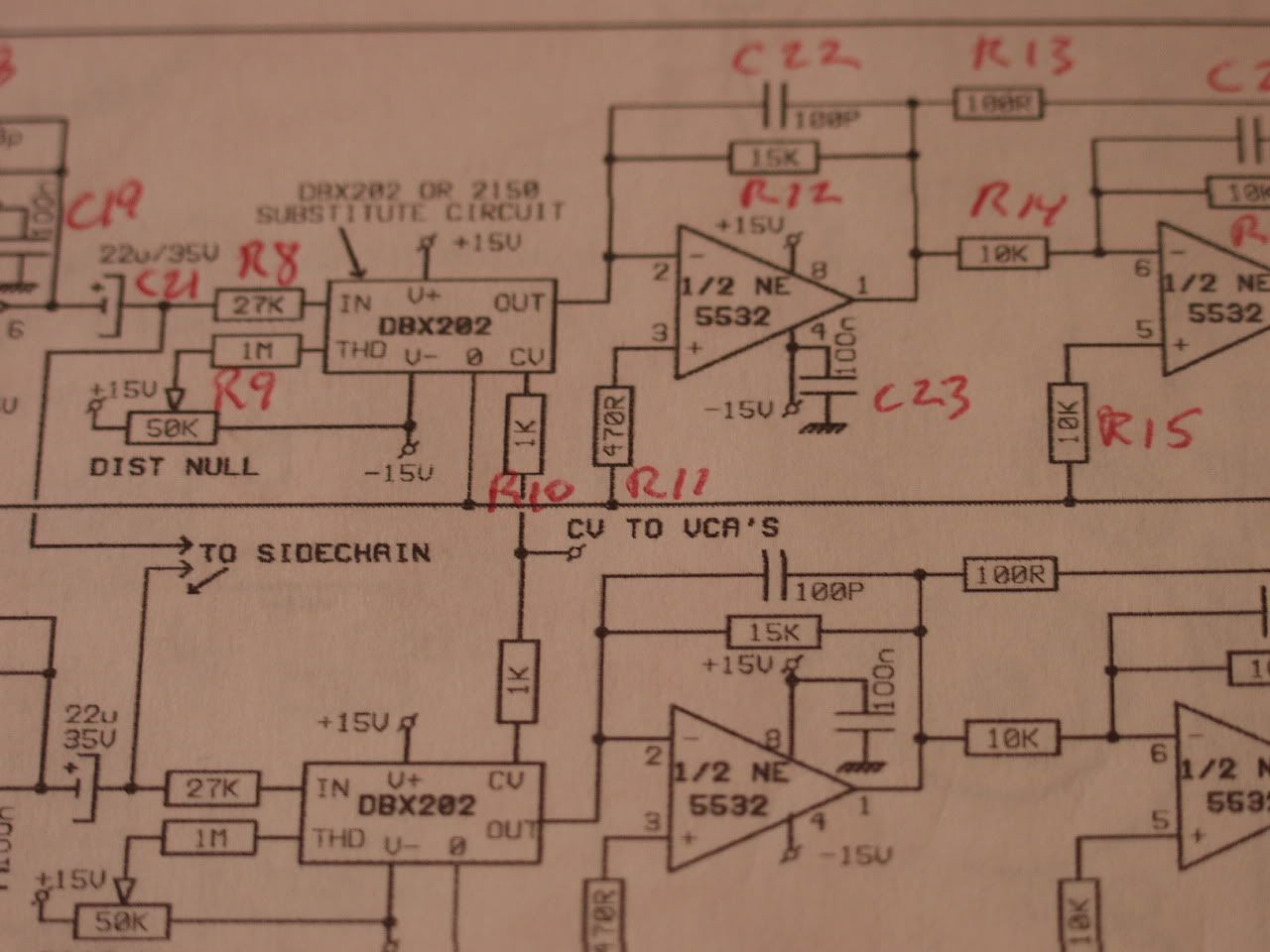
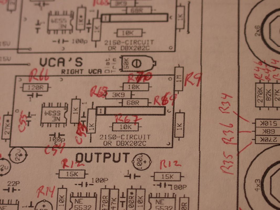
To answer breifly, anything inside the boxes take out and everything outside the boxes leave in.


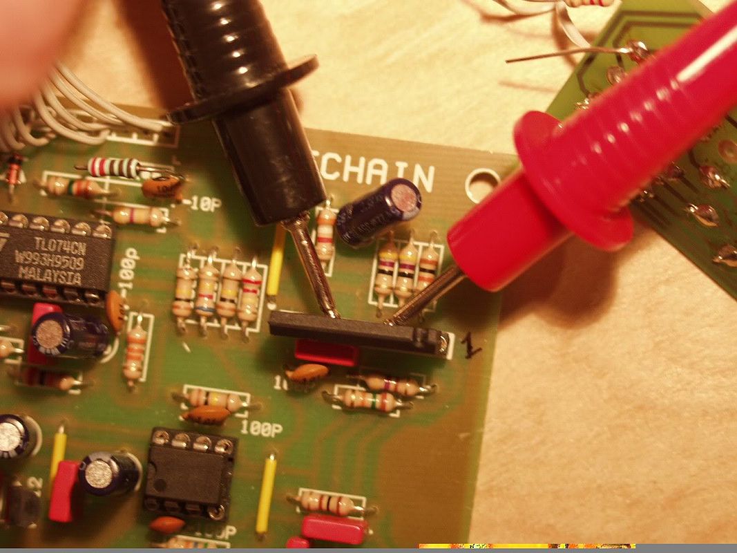
Compression is grossly distorting at virtually every setting. As soon as compression is dialed out with the threshold pot the audio cleans up to normal again.
Any ideas?
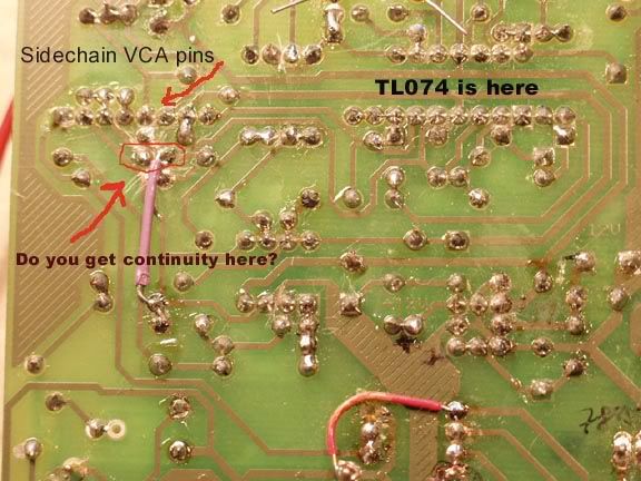
") ), then check waveform at your "timed" cv, coming from the Attack/Release circuits..
), then check waveform at your "timed" cv, coming from the Attack/Release circuits..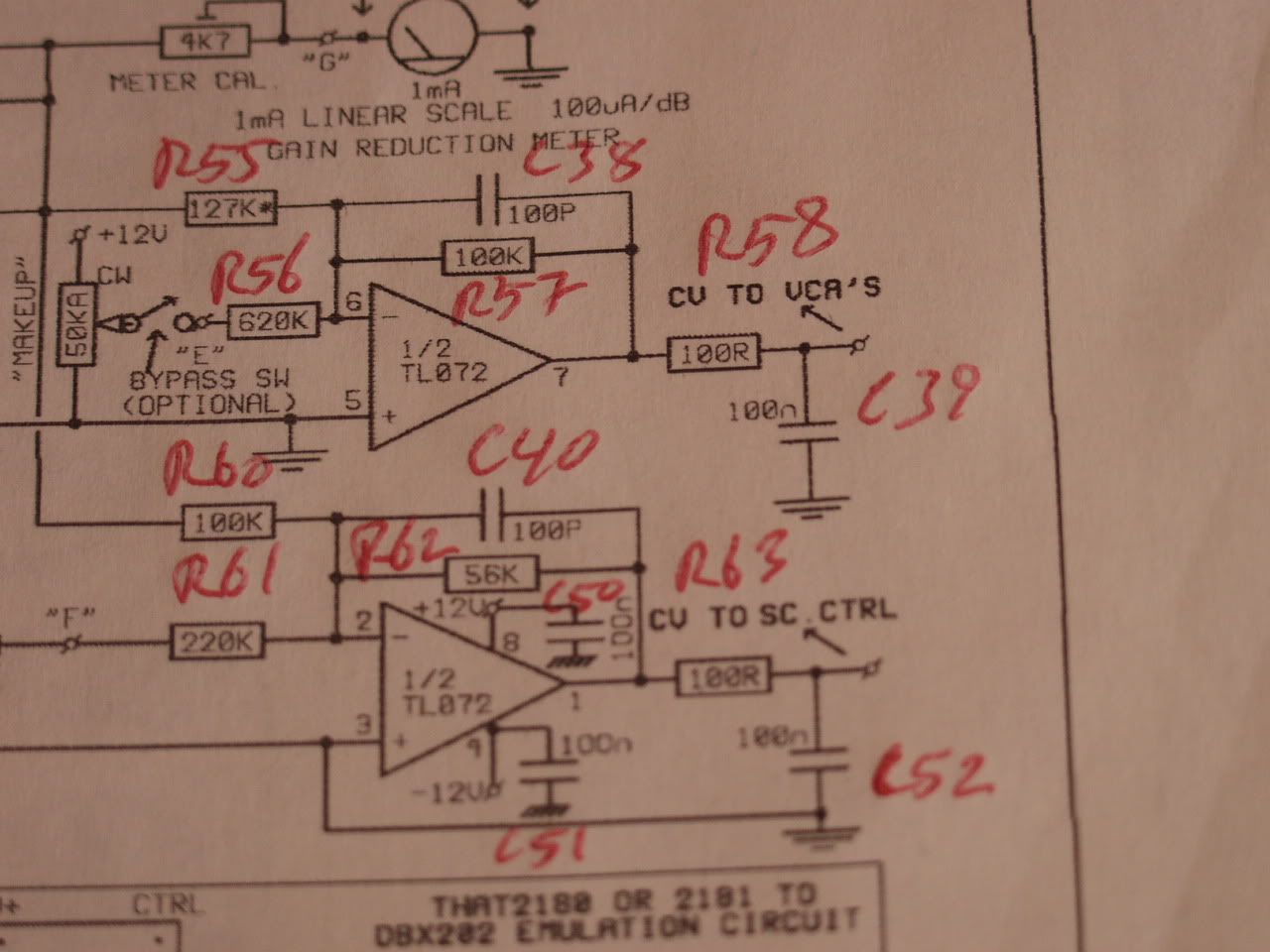
so this should be no problem since the opamps are equal?