GSSL HELP THREAD!!!

GroupDIY Audio Forum

Help Support GroupDIY Audio Forum:

This site may earn a commission from merchant affiliate links, including eBay, Amazon, and others.
Hi,

Since I had a little background noise on the SSL,
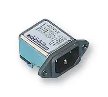
I'm wondering if it's important to use a a FILTER IEC connector on the SSL, like this:

42253294.jpg
 
Very often, filter IEC connectors are worse than nothing on fully-analouge equipment. Save those for thingys that contain switched-mode psu's and/or computers.

The problem is that the filtering of the power is done by dumping the dirt into the 0V/Ground tap - and we like our grounds to be as clean as possible

Jakob E.
 
Jakob, thanks for the PM.

Yes, the slower release settings are not distorted, depending on levels. This means my un-rectified AC is being filtered in the A/R circuit, as you mentioned. It's yet another confirmation that the problem is the rectifier, I believe, as my previous readings suggest. (Also see my half wave scope image on page 119, which makes me suspect half the wave is being rectified.)

If half the rectifier is working, why are my readings showing AC at all points on the rectifier?

What comprises the rectifier in this circuit? Is it the 4 diodes around the TLO74? (2 on pin 1, 2 on pin 14)

Which stages of the TLO74 are inverting the signal? (It's a little confusing to figure out how the rectifier works; also there are links to the ratio control.)

Can you explain the rectifier, and which side is which polarity, please?

Looking at the polarity of the my half wave scope image on page 119, can we tell which side of the rectifier is not working? (side on pin 1, or pin 14?)

thanks.
 
I'm curious if not having the power on LED or the 1m resistor for the LED connected(I was not going to use these since I have lighted switches), as well as not having the meter or the meter resistor connected will affect the functionality/sound of the unit, just got ahead of myself and forgot to attach these? It doesn't look like it should on the schematic but I'm new to DIY so I might be wrong. I just plugged in my unit and it is very distorted and the sound is cutting out, so I know something is not right but just wanted to double check the obvious first before spending hours reading this thread again, troubleshooting and checking voltages.

Thanks
Brian
 
Well,
got 3 GSSL working just fine..... and just as I started patting myself on the back...
I tested the 4th one... and... murphys law kicked in.


Audio passes through but the meter is pegged and it's maxed out with compression. The makeup gain works... Just as if threshold is turned to max. Bypass works. Checked for shorts, couldnt find any.
Any ideas o' worthy forum ...???
Thanks!!!
 
[quote author="tommypiper"]
Yes, the slower release settings are not distorted, depending on levels. This means my un-rectified AC is being filtered in the A/R circuit, as you mentioned. It's yet another confirmation that the problem is the rectifier, I believe, as my previous readings suggest. (Also see my half wave scope image on page 119, which makes me suspect half the wave is being rectified.)

If half the rectifier is working, why are my readings showing AC at all points on the rectifier?
[/quote]

If you look at your scope, you should find that this is NOT AC, but a varying amount of DC. The important thing is that the voltage is no longer symmetrical around ground, which it would be for AC.


What comprises the rectifier in this circuit? Is it the 4 diodes around the TLO74? (2 on pin 1, 2 on pin 14)

Which stages of the TLO74 are inverting the signal? (It's a little confusing to figure out how the rectifier works; also there are links to the ratio control.)

Can you explain the rectifier, and which side is which polarity, please?

The rectifier is the two tl074-sections with diodes around, each taking care of one half-wave. Try looking up some opamp application notes for an explanation of how this circuit works. The ratio switch just changes rectifier gain and adds a bit of offset.
Looking at the polarity of the my half wave scope image on page 119, can we tell which side of the rectifier is not working? (side on pin 1, or pin 14?)

Nope, that isn't clear to me, sorry..

Jakob E.
 
[quote author="gyraf"]
If you look at your scope, you should find that this is NOT AC, but a varying amount of DC. The important thing is that the voltage is no longer symmetrical around ground, which it would be for AC.[/quote]
If it's DC, then I don't have a rectifier problem? No wonder I couldn't find it. Sheesh.

So this means I'm getting pollution in the sidechain somewhere - it's not AC getting past the rectifier. Holy corrumba.
 
OK, checking everything again and still can't find the problem.

What voltages am I supposed to be seeing in the sidechain?

Are my voltages on the TLO74 from page 121 correct?
 
My two GSSLs are in storage at the moment (thanks to Katrina :evil: :twisted: )... If you don't have this working by the weekend I'll make an effort to get out there so I can compare voltages with you.
 
Noisewise, is it better to use the input buffer amps (NE5534) there in unbalanced configuration (neg input to ground) or bypass them and connect the input signal directly to the V/I converter (27k resistor in this case, via the 22 uF cap, ant to the sidechain 47k summing resistors of course, and assuming the output impedance of the sourcing device is low enough, ~600 ohms or so)?
 
I just finished my GSSL and it seems to be doing its job of compression. Bypass works, makeup gain works, ratio, attack, and release seem to work, but the threshold doesn't work. I am getting some very heavy pumping with 4:1 and 10:1 ratios with the attack and release settings at in-between fast and slow. Can anyone shed some light in this matter?

Thanks,
Adam
:sam:
 
Does the 10 pin wire set that goes to the control board affect the output of the signal? My meter is giving me a constant signal on input but when I move the pcb around my output signal goes in and out and I am trying to trace the source of the bad wire. It's either the output wires or the control board wires.

Adam
:sam:
 
good news. after a truly mysterious group of problems with my gssl it all came down to a bad pcb trace. it was completely invisable and was only detected after extensive probing. but it works! and sounds amazing to boot.

it is a neat feeling to make one of these and have i work right. as ive read from others, it is addictive. count me in!
 
Enochjensen-

congrats! I've heard of this from someone earlier in the thread. What trace was it?

Greg-

thanks, if you get a chance to check voltages. I think that's my next step is to compare readings with a working unit. I may have to build one in order to get this one working, that may be the only way to definitively troubleshoot, lacking further information.
 
Back
Top