Hammond Inductor Value's

GroupDIY Audio Forum

Help Support GroupDIY Audio Forum:

This site may earn a commission from merchant affiliate links, including eBay, Amazon, and others.

airtech

Well-known member
Joined
Jul 19, 2005
Messages
79
Location
Long Beach, California
Hi,

I've got a vibrato line box from a Hammond M3 that is on it's own, out of the organ it came from. There are 16 inductors inside and I was wondering what the inductance values are for each of them. I read somewhere that they are 500mH each, but just wanted to confirm. I am going to be using these for a project to simulate electric guitar pickup inductance...I'm building some re-amp boxes for my studio.  The only test tool I have is a fluke 187 rms meter so I probably won't be able to test for inductance. 

Thank you,
Nate
 
> The only test tool I have is a fluke

No signal generator? No resistors?

Signal loss thru an L-R filter gives inductance.
 
I have a built in signal generator with my Pro Tools system, no stand alone, and I do have resistors.  I've never checked for inductance before.  Each of the inductors resistance is 435-437 ohms.
 
Here is a link to some information that I read regarding the coils. http://www.jhaible.com/scanner_vibrato/jh_scanner_vibrato.html

Would the 500 mH measurement be the total inductance of all coils in series or the individual coil inductance?

Any help would be appreciated.  The individual coils have two wires coming off them and measure 1.5 inches in diameter with a 5/16 hole at the center of each.  The model number of the coil is AO-21842-3, 172645.

Thanks,
Nate
 
airtech said:
Here is a link to some information that I read regarding the coils. http://www.jhaible.com/scanner_vibra...r_vibrato.html

Would the 500 mH measurement be the total inductance of all coils in series or the individual coil inductance?

Any help would be appreciated.  The individual coils have two wires coming off them and measure 1.5 inches in diameter with a 5/16 hole at the center of each.  The model number of the coil is AO-21842-3, 172645.

Thanks,
Nate
Link is 404.
 
airtech said:
I have a built in signal generator with my Pro Tools system, no stand alone, and I do have resistors.  I've never checked for inductance before.  Each of the inductors resistance is 435-437 ohms.
the best solution is probably to put a capacitor across the inductor, feed one side with the generator and mesaure at the other side. You should observe a noticeable notch in the frequency response. In order to make it more visble, you should load the meauring side with a resistor; about anything between 10 and 100 ohm. Now you have to choose the capacitor value so that the notch frequency is within the audio BW.
For 500mH, a 47nF cap would put the notch at about 1040 Hz.
The formula is L=1/[C.(2pi.F)²] Watch out for leading zeros (or exponents)!
 

Attachments

  • L measure.jpg
    L measure.jpg
    63.5 KB
> the procedure to find the inductance

This is basic AC Theory. You need to swallow some R-L-C concepts if you are going to do fancy audio.

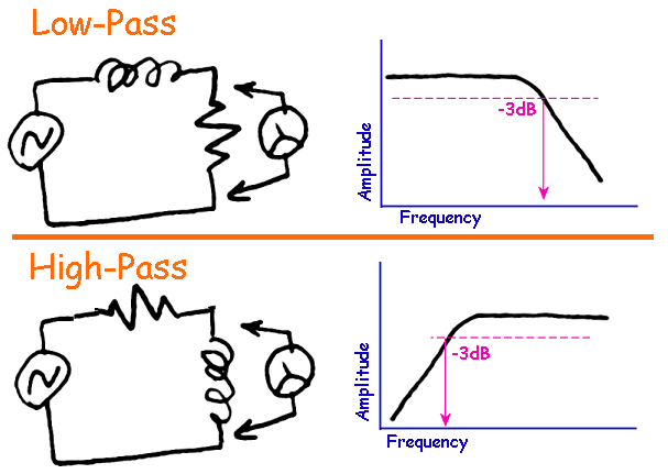
Put a coil and a resistor in series from a variable frequency AC/Audio source. Measure the voltage across the coil or the resistor. There are two cases:

vUbFG4X.gif


You may recognize these from loudspeaker cross-over networks.

At the frequency where the output is 3dB down from the "flat band", the reactance of the coil is equal to the resistor. Coil reactance formulas can be found. When you want frequency in Hertz they will have 2Pi in them. In fact coils are easy: Z = 2*Pi*F*L

There is theory and there is real-world. All coils have dead resistances as well as inductive reactance, and for many audio chores we are lucky to get the inductive reactance "much" higher than the dead resistance. So TIP: measure the DC Ohms (plain ohm-meter) of the coil. Multiply that by about "10". Use a resistor of about that value.

Abbey's L-C technique is fine. More accurate. But with true mystery coils there is the question of what capacitor and what resistor to start with. Probably more likely to get confused.

> a project to simulate electric guitar pickup inductance...

Ah. Then in some sense your parameters are "fixed". You want to resonate with 300pFd-1,000pFd at about 3KHz to 5KHz (the value of guitar-cord capacitance and guitar pickup/cord resonance). So you could just set up your circuit between bland source and flat amp+speakers, and swap coils until you hear "a rise of the Zing" which makes the source more guitar-y. And as a first-cut, you "know" the coil has to have a DC Resistance nearly as high as a guitar pickup, thousands of Ohms. You can set-aside any coils showing less than maybe 500 Ohms. (Or re-compute the filter with large C and low R, but you may not yet be ready to do that.)

> a project to simulate electric guitar pickup inductance...

There *is* a $3 transformer which happens to have about the right inductance for "guitar pickup". I do not recall the number, but I would be looking at cheap 10K windings. Specific experince can be found on fuzz-box forums. (Many fuzzes rely on "seeing a pickup" to get the right effect, so fake-pickups are needed in many-effect guitar pedal boards.)
 
here is a discussion on measuring pickup inductance that may help you with this project,

http://www.syscompdesign.com/assets/Images/AppNotes/guitar-pickups.pdf

a pickup will have a high DCR due to the small wire, 8K ohms is typical for a single coil,

and there is a lot of capacitance so there will be a rersonant frequency of each pickup,

you also have a pot across the pickup, maybe 250K, so you have series and parallel resistance, stray capacitance, and a tone circuit, and a guitar cord,

a cool experiment would be to pug a cord into a guitar and run a signal thru there, maybe 100 mv which is close to a medium level pickup output,

use AC current, frequency and applied voltage to figure out the inductance of the system for various frequencies,

maybe go to a music store and see if they will sell you a junk pickup to use,


> a pickup will have a high DCR due to the small wire

Yes, and a "same value" inductor "may" have lower DCR both because it is not a wide-open core and because it might be larger than we'd want for a pickup.

Still anything under 500 Ohms DCR is unlikely to be in the range he wants.
 
Let's say we scale down the impedances, instead of 4H/6kohm/1000pF/250k*, we get 500mH/450ohm/8000pF/27kohm, which yields very comparable results.
The nice thing is that the OP wants to emulate a low-Q circuit; it is always easier to reduce the Q by adding series resistance or increasing load, than the contrary.

* typical of a Stratocaster with a 15ft cord
 
here is an inductance plot using a single generator feeding the pickup with a current meter in series,  400 mv AC applied.

this coil behaves more like a gapped inductor, as there is a lot of air in the core,
that is, current stays about the same regardless of the frequency as the core (magnets) are not a big part of the inductance as the 10,000 turns,

that rise in the lo freqs is due to DCR not being corrected for, (impedance curve)


Attachments

  • single-1.jpg
    single-1.jpg
    79.9 KB
here is the same graph magnefied without the low freqs,

there is a slight rez peak at 3 k hz,

this is a crazy coil wound with #48,

next we will check a single coil with more normal wire gauge and dcr, (11k ) and turns,


Attachments

  • single-2.jpg
    single-2.jpg
    49 KB
here is a side by side plot with the second pickup which has less turns and bigger wire, lower DCR and a bar magnet instead of magnetic pole pieces, not much of a rez peak,


Attachments

  • single-2.jpg
    single-2.jpg
    75.9 KB
here is a plot of the current in the inductor, flat for the bass freqs and drops at the high freqs, a normal ungapped steel core inductor would have an increase in current at the higher freqs, so that Hammond inductor would probably not be an accurate replacement for a guitar pickup as the freq curves for inductance and current would not match very well, you need an air core inductor or an inductor with a big air gap,

that jump in current is when i switched freq ranges on the HP generator, voltage pops up a bit at the low end of the dial,
 

Attachments

  • single-2.jpg
    single-2.jpg
    77.2 KB
here is a vid on random vs machine winding of a pickup, it has a better freq curve than the crude method we used,

https://www.youtube.com/watch?v=CW_ZW3aMMB8
 
Back
Top