With a bit of renewed interest in this thread I thought I might as well update with a couple of pictures.
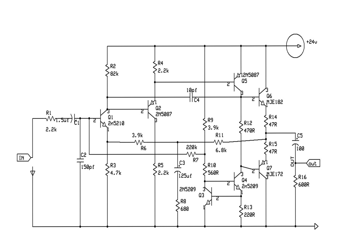
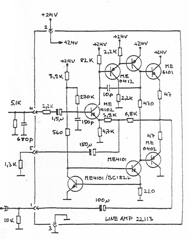
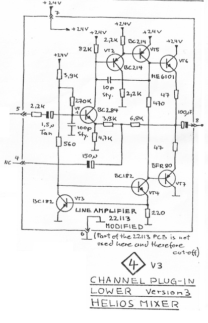
The first picture is of a line module with only the HPF retained (no other eq). Unbalanced insert is added (I'll eventually work out the most appropriate place with a bit of trial and error). In hindsight I could have dispensed with the 1 transistor HPF buffer and just used the 22113 which would have ended up with that amplifier probably running at a happier operating point. Since I will build a few of these purpose built line modules I was thinking of building a couple of 2128-2128 modules to compare with the 2128-22113 modules.
This module could easily become a pre if the input transformer were changed and a gain switch were added (swap out the 0-20-40 pad that is currently in place). Module is unbalanced out but you could probably squeeze an output transformer in there if you cramped thing up a bit. I'll look to use this for something like an effects returns.
The second and third pictures are of a prototype router module. I think I almost know how I will proceed with this to the second (and hopefully the last) prototype. For the sake of headroom, and driving auxiliaries, it would have been better to use the 22113. The 0V layout was wrong, a bit overkill in places and a bit too much floating going on. Resistor and pot values, auxiliary loading also largely wrong. Was a good learning experience.


![Soldering Iron Kit, 120W LED Digital Advanced Solder Iron Soldering Gun kit, 110V Welding Tools, Smart Temperature Control [356℉-932℉], Extra 5pcs Tips, Auto Sleep, Temp Calibration, Orange](https://m.media-amazon.com/images/I/51sFKu9SdeL._SL500_.jpg)


