


Swedish Chef
Well-known member
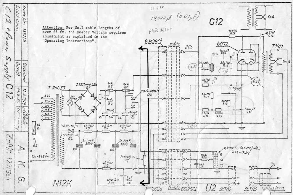
I have been trying to get my thick head around the maths for the Hi Pass filters such as on the C12a and C12VR schematics.
(Apologies for being un-able to find an online schem to link to and not having my camera with me!! Will get them up ASAP)
In the C12a circuit there is a tapped inductor which is switched in to be strapped across pin 2 and 3 (hot and cold) of the output XLR. There is no spec on the inductor for the C12a schem but on the C12VR it specs 520mH, although there are some odd looking caps in-line with the 'Cold'/ pin 3 line.
According to my calculations and experiments this gives rise to a rather high frequency for a bass roll off isn't it?
I am confused.
chef
EDIT


![Soldering Iron Kit, 120W LED Digital Advanced Solder Iron Soldering Gun kit, 110V Welding Tools, Smart Temperature Control [356℉-932℉], Extra 5pcs Tips, Auto Sleep, Temp Calibration, Orange](https://m.media-amazon.com/images/I/51sFKu9SdeL._SL500_.jpg)


