Matador
Well-known member
Does anyone see anything obviously wrong with this topology? It is adapted from one of Sam Groener's designs (which itself seems to have come from the 990 opamp). It is essentially modified to:
a) Use high-voltage current references rather than BJT's that are diode biased
b) Be capable of operating from 400V rails
c) Uses BJT's that have 600V to 800V VCE ratings
I don't expect/need to be able to drive significant output currents, so there isn't a beefy output pair, as it can be difficult to find PNP transistors rated over 1A that can withstand high collector/emitter voltages. In this case, there are two applications: one, to use as a comparator in a high-voltage MOSFET power supply (meaning all that will be driven is the gate of a MOSFET), and the other is to increase the output of a signal generator that can output 10 Vpp max, up to something around 70 or 80 Vpp for testing tube output stages (ones that may even need to partially operate in class AB2). I expect 50mA or less in the worst case.
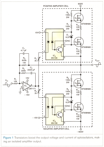
Here is the schematic:

Is there any reason that the dominant pole compensation (C1) would need to be adjusted from moving to higher voltage rails? Sam's original was rated for 80V supplies, whereas I expect to be operating this one between 150V and 400V.
a) Use high-voltage current references rather than BJT's that are diode biased
b) Be capable of operating from 400V rails
c) Uses BJT's that have 600V to 800V VCE ratings
I don't expect/need to be able to drive significant output currents, so there isn't a beefy output pair, as it can be difficult to find PNP transistors rated over 1A that can withstand high collector/emitter voltages. In this case, there are two applications: one, to use as a comparator in a high-voltage MOSFET power supply (meaning all that will be driven is the gate of a MOSFET), and the other is to increase the output of a signal generator that can output 10 Vpp max, up to something around 70 or 80 Vpp for testing tube output stages (ones that may even need to partially operate in class AB2). I expect 50mA or less in the worst case.
Here is the schematic:
Is there any reason that the dominant pole compensation (C1) would need to be adjusted from moving to higher voltage rails? Sam's original was rated for 80V supplies, whereas I expect to be operating this one between 150V and 400V.


![Soldering Iron Kit, 120W LED Digital Advanced Solder Iron Soldering Gun kit, 110V Welding Tools, Smart Temperature Control [356℉-932℉], Extra 5pcs Tips, Auto Sleep, Temp Calibration, Orange](https://m.media-amazon.com/images/I/51sFKu9SdeL._SL500_.jpg)