> right that the only way to do it would be to actively buffer it with something very high impedance
NO, there are many ways to do it. A very low-impedance input is the abstract goal. First-order trivial to implement a grounded zero-Z input: we call it "summing amp". The requirement for 2X current multiplication forces a few more parts. And meter-resistance is uncertain. And we now learn that the "10mA" goal is uncertain (tubes may sit at 8mA or 13mA), and that resistance only needs to be "small", not Zero.
And with that 5 ohm resistor, no simple fault from a "150V" line is going to smoke the 19-cent chip.
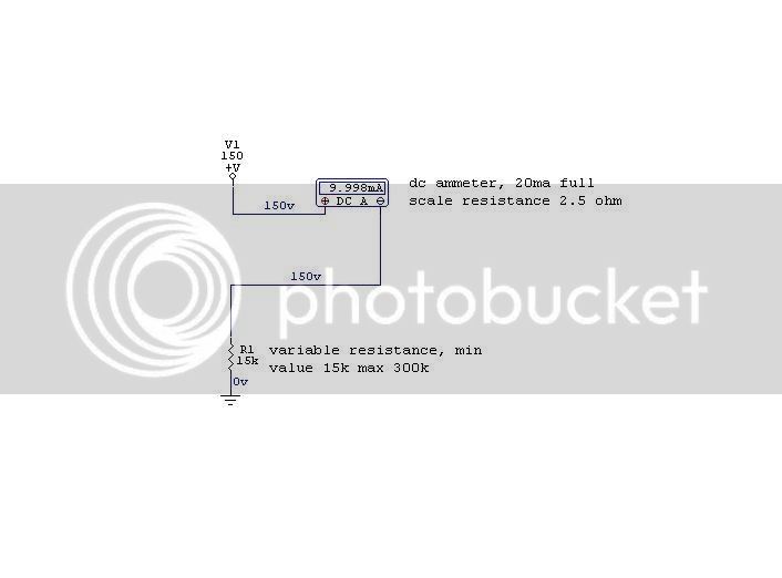
> We have a series resistance of 15k to 300k.
We now know that is a Test Rig. The actual application is "grounded cathode" with a varying grid voltage and cathode current. The ab-max voltage at Zero current is about B+/Mu, maybe 30V (though some brutal low-Mu stages can run higher). The actual happy-working cathode voltage MUST be dang near zero, or GR won't happen and THD is not canceled. It might be a couple volts, though under 1V might be better. It can't ever go negative. The idle current is the maximum possible current. For any reasonable number of suitable tubes, it is unlikely to flow 20mA; for most reasonable tubes, 2mA to 10mA.
The plan above, drawn before my second cup, still works, with one caveat. If indeed the meter is 20mA (no internal shunt as JR guesses), then the chip needs +5V to +35V power (not shown) at up to 20mA, which is generally awkward in tube gear. If your outputs are P-P hot 6V6 or bigger, you can tap the cathodes for power, but the 0-20mA draw will skew the output bias. That's probably a general problem for this 20mA meter in simple tube gear.
Frankly it might be as simple to double-up or triple-up your vary-Mu tubes to bring VCA draw up to 20mA: same total demand from B+ compared to a drop-and-waste meter-buffer supply, but some improvement in deep-compression performance.
To trim sensitivity, adjust the 5 ohm resistor. Or since few-ohm pots are rare, and the LM324 input is infinite, and vari-Mu tubes won't care about a dozen dead ohms, raise the 5r to 10r and shunt it with 1K or 100K pot, trim to suit.


")


![Soldering Iron Kit, 120W LED Digital Advanced Solder Iron Soldering Gun kit, 110V Welding Tools, Smart Temperature Control [356℉-932℉], Extra 5pcs Tips, Auto Sleep, Temp Calibration, Orange](https://m.media-amazon.com/images/I/51sFKu9SdeL._SL500_.jpg)


