I want to build a tube mic today - Suggestions are welcome.

GroupDIY Audio Forum

Help Support GroupDIY Audio Forum:

This site may earn a commission from merchant affiliate links, including eBay, Amazon, and others.

northsiderap

Well-known member
Joined
May 8, 2005
Messages
223
Location
Michigan
First of all - Take it easy on me. This is just a hobby for now.. I have done some work on tube amps tho.

I have a few old capsules, power supplies, and tubes laying around and I thought this would be a fun project. The victim will probably be an Oktava MK-219 capsule in a handmade body.

I have available either a 12AU7 or 6AU6. The schemo is what I have read and understand so far about tube amps -

I cathode biased to @ -3V. This preamp should amplify up to 1V... I have the plate running at @135V and 8mA.

I have a stock of transformers to use - probably try to get that 10k load from a transformer.

I noticed that this mic from www.gyraf.dk looked pretty much like a basic tube stage, so I am eager to try it out... It looks like a global feedback from the OP Xformer. Something I don't know how to calculate for yet.

http://www.gyraf.dk/schematics/221bschem1.gif

Anyway, here is my schematic. The capsule polarizing resistor is just a guess until I capacitance test the capsule I'm going to use. Could the capsule polarization be a voltage divider without ill effects?

Also, will this be enough output? I simulated a @7mV output for a 1mV capsule input -before a OP Xformer step-down. I also drew a schemo with an FET before the tube stage if I need extra gain.

Mikey.jpg
 
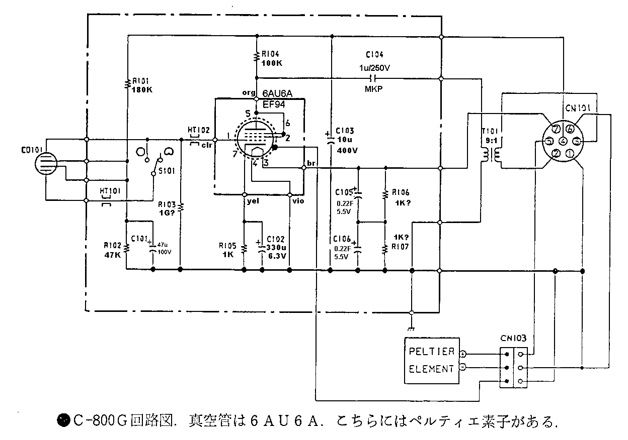
12AU7 is not suited for mics, the 6AU6 is a better choice. Look at the Sony C800 schematic.

And btw, you need much higher input impedances to drive the tube stage with a condenser capsule. Think 1G Ohm as rule-of-thumb.

Jakob E.
 
What Jakob said.

And 8mA is probably way, way too much current for a small signal amp... think .5mA - 2mA.

Peace,
Al.
 
I've scrounged up the parts to make a 230V PSU - - - I'm probably going to use a voltage divider to get the capsule to a nice safe 60-65V.

Studying the G7 http://www.gyraf.dk/gy_pd/g7/gic_s.gif and other tube mics, the only things I don't understand now are:

1) the use of two caps and a (voltage divider?) in the cathode bypass.

2) PPL mentioning the output configuration/impedance through a step-down xformer severely affecting headroom. Anyone have more info on this?

3) Calculating the feedback resistors... Any help here also? I'll probably opt NOT to put in the feedback R, but it'd be nice to know.

Thanks all!!! :guinness: :sam:
 
1) the use of two caps and a (voltage divider?) in the cathode bypass.

To allow partial feedback.

2) PPL mentioning the output configuration/impedance through a step-down xformer severely affecting headroom. Anyone have more info on this?

Never heard about that - what exactly do you mean? There's no headroom problems in the G7 circuit (nor in all the other classics based on this architecture)..?

3) Calculating the feedback resistors... Any help here also? I'll probably opt NOT to put in the feedback R, but it'd be nice to know.

Depends on actual gain - try different resistors to fit..
 
Northside;

Do it and have fun, learn.

But be warned Gus will not like your results
as he hates the "Oktava MK-219 capsule".

After you finish that project stepup to a better
797 audio capsule, on your second project.
 
Looks like what I'm building is going to be similar to the C800G. I have the tube, MK219 capsule, & most of the resistors & caps.

What I don't get is how the capsule seems to be 'floating' from ground... Most other designs I've seen seem to require the diaphragm to be grounded.

If this won't work with standard capsules, I'm going to have to go with the G7 style capsule polarization voltage with the 1G ohm resistor after the voltage divider.

I would think that more mics would use this design if it fit a standard capsule - Less parts.
 
[quote author="northsiderap"]
Mikey.jpg
[/quote]

R1 (polarizing) and grid leak resistors too low. You lose bass. Capsule capacitance
= 60 pF. and 1/omegalow=R*C
use G1 resistors for polarization and leak.
And be careful... polarization voltage is design parameter of
capsule. Usually around 60 V. Use divider!!!
Tube also uses bit higher grid leak resistor - somewhere is better to underheat it.

xvlk
 
Here is more of what I'm doing now...

MicSchemo.jpg


I'm hoping that the capsule floating from the ground is going to work... If not I'm going to go back in and do a G7 style voltage divider with grid cap.

The capsule is above 50V now, just happened to be the resistors I had laying around.

All of the components are accounted for except for the 3-5uF output cap...

I still don't have a super high-quality 1Gig, but I have a 5% I'm going to substitute just to get it up and running.
 
:grin:

I found a mic body at the dump. I jumped right in the rusty steel pile for this one...

An eleven inch copper plated brass tube with a *Nice* patina. Yum. I just hope that the dang thing sounds as vintage as it will look now...

I'm naming it the 'NLA-001' for 'North Lake Audio (LLC) - Model 001.'

MicBody.jpg

* Note the mystery fluid leaking onto the bed. Hope it's not too toxic. :!:
 
Yea, that circuit should work but you might want to make C3 smaller so you don't need an electrolytic there - and raise R1 and R6 to 2 Meg and 470k (roughly). I often do that - no coupling capacitor. That works great if you don't have multipattern to deal with so you don't need exact voltages worked out across the capsule.

-Dale
 
:thumb:

I did some work on the mic, not wired up yet - - - The capsule voltage divider is sandwiched between the two big caps above the OP to Xformer cap. Behind the circuit board is this plastic backed metal so no high voltages will ever short to ground (hopefully.) I also have metal wiring harnesses that will snake through the thing and hopefully shield a few uDBs of RF and noise :guinness:

All of the big electros are power filter caps. There is an electro in the cathode bypass, but I see some of you paralleling this with another cap (Ceramic Disc? Polystyrene? Polypropylene? Metal Film?)

Also, the load resistor looks like maybe a 3/4 watt... I figured it'd be running under a half watt anyway. Tell me if I'm wrong before I plug it in.

MicDIY2.jpg

The picture's kinda blurry - having trouble with my camera...

I think I'm hooked already - - - Despite all of her imperfections.

This mic is almost completely 'recycled.' The only parts I will have bought are :

1) The capsule - $40 US
2) The Marinaire transormer - $50 US

The rest of it is from an old uMatic tape deck and an old tube television set someone was getting rid of...

Now I have to find a good way to attach my grille... Where's a metalworking META when you need one?
 
[quote author="northsiderap"]
MicSchemo.jpg

[/quote]
Too hard microphone polarization divider can cause capsule burn out.
(But is noise-optimal :) )
C3 maybe somewhere like 10 nF and divider may be of some 100 Meq Ohms Thevenin equivallent. (multiply all resistors in divider by 100 X)
It is capsule and/or tube spark protection. It may safe capsule. If you
can not safe capsule, do nothing.
Look at old Neumann schematics...

xvlk
 
[quote author="northsiderap"]I was going to add a 2meg ohm resistor right before the capsule to slow the current down just a little...[/quote]

Come again? :?

Peace,
Al.
 
[quote author="xvlk"][quote author="northsiderap"]
[/quote]
Too hard microphone polarization divider can cause capsule burn out.
(But is noise-optimal :) )
C3 maybe somewhere like 10 nF and divider may be of some 100 Meq Ohms Thevenin equivallent. (multiply all resistors in divider by 100 X)
It is capsule and/or tube spark protection. It may safe capsule. If you
can not safe capsule, do nothing.
Look at old Neumann schematics...

xvlk[/quote]

I'm assuming you are saying to not throw so much current to the capsule - - - I will look at old Neumann schematics today...

I have a few problems - - - I'm running out of resistors. I'm trying to use only the resistors I have in stock... I do have a couple of smaller wattage 2Meg and 2.2Meg left though, so I thought I'd put one after the voltage divider.

Anyone know how to read those giant vintage resistors? They are the size of my pinkie and have 5 or more stripes on them...

eg. yellow-purple-orange-black-yellow
eg. red-purple-red-white-yellow

???? :?:
 
[quote author="northsiderap"]I'm assuming you are saying to not throw so much current to the capsule[/quote]

Err... the capsule acts as a capacitor! Am I missing something here???

[quote author="northsiderap"]I do have a couple of smaller wattage 2Meg and 2.2Meg left though, so I thought I'd put one after the voltage divider.[/quote]

You mean between the polarization voltage and the backplate? use a 1G resistor. And make that divider higher impedance!

[quote author="northsiderap"]Anyone know how to read those giant vintage resistors?[/quote]

Yes. With a VOM! :wink:

Peace,
Al.
 
I guess I just assumed that impedance/amperage wouldn't matter since the voltage divider isn't in the grid path...

Maybe AC signals work through a capacitor (capsule) and the impedance on the backplate might matter after all....

I thought I'd throw that 2.2meg immediately after the backplate and call it good.... But I do have a few 1gigs and other resistors left to mess with.

The C800G has lower resistor values in the voltage divider though... As I understand it the grid resistor is actually more like 500Meg also.

Sony_C800G_Schematic.gif
 
I'd recommend reading Gyraf's guide to the G7 microphone which he designed.

It is very well documented.
 

Latest posts

Back
Top