You are using an out of date browser. It may not display this or other websites correctly.
You should upgrade or use an alternative browser.
You should upgrade or use an alternative browser.
IDEAS: "a differential discrete jfet input stage"
- Thread starter tv
- Start date


Help Support GroupDIY Audio Forum:
This site may earn a commission from merchant affiliate
links, including eBay, Amazon, and others.
clintrubber
Well-known member
[quote author="tv"]Hehe jensen take on TL/H/6791-24 from an32 pg.8 ") [/quote]
[/quote]
Yep, various places where it emerges ;-)
[/quote]Yep, various places where it emerges ;-)
Uhh, why not more ? :wink: :roll:Such circuit is a contender for a single-ended "ultramojo" onboard preamp.
mr coffee
Well-known member
tv,
Do you get that the Duncan active pickups use lower impedance coils with a lower output level and then use the onboard preamp gain (18 db from the data sheet you linked to) to make the output comparable to a high impedance passive pickup? That's why they pick up less noise from the environmental noise sources(the lower impedance of the windings) but tend to hiss more (the preamp gain) than high impedance pickups.
And do you get that you need to change your pickup coils to get the benefits of the EMG\Duncan approach to lessen noise pickup? Most of the difference in environmental noise pickup is from lowering the impedance of the pickup coils, not the differential preamp business.
With the EMG\Duncan approach, one coil is fed into the non-inverting input to of the JFET differential amp and the other coil is fed into the inverting input. So they aren't in series or floating. One end of each coil is grounded or at least connected to a common bias voltage. Yeah, you don't need series input caps if you pick JFETs and source resistors that will bias right. But you have to throw away all that gain in the differential preamp because high impedance pickups already have plenty of output voltage (and will overload it otherwise).
If you are wedded to the current pickups, do they have 4-wire outputs?
If so, you can run both coils separately to a differential amp with degenerative gain or - more prudently, noise-wise - through a separate preamp like the ones you already have made and then combine them with a trimpot to balance out the hum pickup. I assume you can figure out how to connect the coils out of phase. That will lessen the hi-impedance pickup junk a little bit copying the principle of the Duncan-type differential topology.
But be prepared for the tone to be WAY different and I'll bet you won't like it. Part of what shapes the frequency response of the passive humbucker designs is the fact that the coils are (usually) in series and the inductance of the two coils in series rolls off the highs in a unique manner giving a Q peak and rolloff which is slightly different from a classic 2-pole LPF because the second coil is an inductor in series with the output of the first coil, plus there is all the distributed winding capacitance of both coils. Think of the difference between the sound of a humbucker with the series coils-single coil switch sound change.
The Duncan and EMG designs use low impedance coils that don't have a resonant peak in the audio range, so they sound flat and "acoustic-y" without the tone shaping circuitry inside the preamp (the low pass filter with a cutoff frequency in the audio range and a Q which give a sizeable reasonant peak just before cutoff). From the Duncan data sheet you pointed to, you can see they EQ'ed the bridge and neck pickup differently with F sub c of 750 hz on one (I forgot the other- check the data sheet if you're interested).
But as long as you have high impedance coils, it's really not going to get much better on environmental noise pickup. It just the physics of it.
Hope this clears it up for you. If you can stand the current level of environmental noise pickup with your guitar for another 15 years, be happy with what you've got and forget the EMG\Duncan stuff. If you can't, you're in for buying an EMG or Duncan set OR spending a LOT of time rewinding your current pickups with larger wire and less turns and tweaking the lowpass filter F sub c and Q to get it to match your perfect sound.
Of course, as always, when you DIY it it will be to exactly your ear and taste. Sometimes it's worth it to me.
Best wishes with your project. :green:
Yo, MrCoffee, you sound like a highschool teacher no offence
While everything you said is true and perfectly logical (you forgot alembic who afaik pioneered the underwound pickups and lowpass filters), carvin feels slightly differently on the subject (and simpler):
http://www.carvinmuseum.com/pdf/guitarbass/a500-b3-activebassmodule.pdf
This is bass onboard pre with floating pickup inputs (can't say for sure, but hypothetically it should be connected similarly to alembic, with exception that alembics are underwound). As it seems there isn't anything in that pickup that is connected to electrical ground.
They -for sure- must have calculated some sort of benefits to that and I highly doubt it's cost-effectiveness. Their other pres also have ferrite beads stuffed-in so I deduce that they spent some time researching general rfi and stage/studio environments. I don't think this is just a way to stuff another mc33178 into the board and call it a day ... there must be a performance benefit, or else they wouldn't do it. And I also think the pickups aren't something "special" either, so ... this must be applicable elsewhere, floating designs are pretty common in audio, or are they rare?
As I said before (repeating again) I want sound of my pickup but lower the buzz and fizz. Floating design seems like the ticket, now what remains is to find out as simple as possible circuit (and wiring in general) with as stellar performance as possible, with inputs @ 0volt potential (and beads ...).
You won the bet. How did you know?
(According to public knowledge, "it takes one to know one")
I can't stand the sound of separately amped coils mixed together. In guitars and basses I want the sound of coil loading another coil, and very lightly loaded with RC elements (i.e. buffered before volume potentiometers - on basses this means no balance pots or alternatively somewhat funny wiring which I won't go into here, unfortunatelly it's "more like an antenna" than other "classic wirings").
Now, please back to the original topic.
no offence While everything you said is true and perfectly logical (you forgot alembic who afaik pioneered the underwound pickups and lowpass filters), carvin feels slightly differently on the subject (and simpler):
http://www.carvinmuseum.com/pdf/guitarbass/a500-b3-activebassmodule.pdf
This is bass onboard pre with floating pickup inputs (can't say for sure, but hypothetically it should be connected similarly to alembic, with exception that alembics are underwound). As it seems there isn't anything in that pickup that is connected to electrical ground.
They -for sure- must have calculated some sort of benefits to that and I highly doubt it's cost-effectiveness. Their other pres also have ferrite beads stuffed-in so I deduce that they spent some time researching general rfi and stage/studio environments. I don't think this is just a way to stuff another mc33178 into the board and call it a day ... there must be a performance benefit, or else they wouldn't do it. And I also think the pickups aren't something "special" either, so ... this must be applicable elsewhere, floating designs are pretty common in audio, or are they rare?
As I said before (repeating again) I want sound of my pickup but lower the buzz and fizz. Floating design seems like the ticket, now what remains is to find out as simple as possible circuit (and wiring in general) with as stellar performance as possible, with inputs @ 0volt potential (and beads ...).
But be prepared for the tone to be WAY different and I'll bet you won't like it.
You won the bet. How did you know?
(According to public knowledge, "it takes one to know one")
I can't stand the sound of separately amped coils mixed together. In guitars and basses I want the sound of coil loading another coil, and very lightly loaded with RC elements (i.e. buffered before volume potentiometers - on basses this means no balance pots or alternatively somewhat funny wiring which I won't go into here, unfortunatelly it's "more like an antenna" than other "classic wirings").
Now, please back to the original topic.
mr coffee
Well-known member
tv,
I give. On with your pursuit of the Holy Grail!
I noticed that the Carvin circuit you cited was located in the Carvin "Museum". Interesting. Didn't know they had one online. Thanks for sharing it.
Well, your statement seems predicated on the presumption that the Carvin circuit is connected to a source analogous to your high impedance pickups. However,...
Please note that prr pointed to a superior topology for a differential preamp (the "standard" 3 op amp instrumentation circuit - a page back in this thread) that would be considerably quieter and have better CMRR than the Carvin circuit applied to high impedance pickups.
You seem to have missed (or dismissed?) prr's contribution (perhaps you didn't know what he meant, or dismissed it since it wasn't the discrete JFET differential circuit you believe EMG and Duncan have developed). It may be what you are after.
The Carvin circuit has 6 db of gain in the first op amp stages plus the over 10 db boost available from the tone controls. It is also run off a 9 volt battery supply (meaning subtract 2 volts, one from each rail for output swing). So if by "aren't something special" you mean you believe they are regular high impedance pickups, perhaps you should compute the headroom that would allow when a bass player hammers with his thumb or goes for the bass-popping style with high impedance pickups, and project what would happen with such a signal passing though such gain stages.
If you hook it up with your high impedance pickups, I'll bet you will find it hisses a bit and overloads\clips more than you will like and that you will end up preferring your old preamp setup.
You are correct, they are fairly common. They are ubiquitous in low impedance audio circuitry, and also in medical telemetry where the preamp input impedance has to be very high impedance because of the inherently very high source impedance (as in electrodes taped to the skin), accompanied by high common mode interfering EMI and RFI voltages, but keep in mind that the range of frequencies of interest is below 100 hz, a fairly narrow bw.
I have done consultant work with a number of guitar players over the years who have sought the same Holy Grail as you, believe it or not. Many of them also sought reduced noise pickup but resisted giving up their beloved high impedance pickups for fear they would be sacrificing good tone.
BTW, I have a tracing of the schematic of the Alembic Guitar electronics if you would like to see it and haven't perused it already. I have also seen the magnet and coil-winding structure of both the Alembic guitar and bass pickup designs before potting and would be glad to share that information with interested parties.
@ Nikolay,
Thank you VERY VERY much for sharing that EMG-81 schematic with us.
There is a tremendous language barrier for those of us here in the USA and other Western countries to overcoming in learning from the writings and discoveries of the many Russian music electronics professionals and hobbyists.
I remain in awe of the incredible ability of those of us around the world with similar interests in understanding and developing musical electronic designs and breakthroughs to share our knowledge with each other through the power of the Internet. Thank you for being part of that bridge for us all. :green:
I give. On with your pursuit of the Holy Grail!
I noticed that the Carvin circuit you cited was located in the Carvin "Museum". Interesting. Didn't know they had one online. Thanks for sharing it.
... there must be a performance benefit, or else they wouldn't do it.
Well, your statement seems predicated on the presumption that the Carvin circuit is connected to a source analogous to your high impedance pickups. However,...
Please note that prr pointed to a superior topology for a differential preamp (the "standard" 3 op amp instrumentation circuit - a page back in this thread) that would be considerably quieter and have better CMRR than the Carvin circuit applied to high impedance pickups.
You seem to have missed (or dismissed?) prr's contribution (perhaps you didn't know what he meant, or dismissed it since it wasn't the discrete JFET differential circuit you believe EMG and Duncan have developed). It may be what you are after.
And I also think the pickups aren't something "special" either, so ...
The Carvin circuit has 6 db of gain in the first op amp stages plus the over 10 db boost available from the tone controls. It is also run off a 9 volt battery supply (meaning subtract 2 volts, one from each rail for output swing). So if by "aren't something special" you mean you believe they are regular high impedance pickups, perhaps you should compute the headroom that would allow when a bass player hammers with his thumb or goes for the bass-popping style with high impedance pickups, and project what would happen with such a signal passing though such gain stages.
If you hook it up with your high impedance pickups, I'll bet you will find it hisses a bit and overloads\clips more than you will like and that you will end up preferring your old preamp setup.
this must be applicable elsewhere, floating designs are pretty common in audio, or are they rare?
You are correct, they are fairly common. They are ubiquitous in low impedance audio circuitry, and also in medical telemetry where the preamp input impedance has to be very high impedance because of the inherently very high source impedance (as in electrodes taped to the skin), accompanied by high common mode interfering EMI and RFI voltages, but keep in mind that the range of frequencies of interest is below 100 hz, a fairly narrow bw.
You won the bet. How did you know?
I have done consultant work with a number of guitar players over the years who have sought the same Holy Grail as you, believe it or not. Many of them also sought reduced noise pickup but resisted giving up their beloved high impedance pickups for fear they would be sacrificing good tone.
BTW, I have a tracing of the schematic of the Alembic Guitar electronics if you would like to see it and haven't perused it already. I have also seen the magnet and coil-winding structure of both the Alembic guitar and bass pickup designs before potting and would be glad to share that information with interested parties.
@ Nikolay,
Thank you VERY VERY much for sharing that EMG-81 schematic with us.
There is a tremendous language barrier for those of us here in the USA and other Western countries to overcoming in learning from the writings and discoveries of the many Russian music electronics professionals and hobbyists.
I remain in awe of the incredible ability of those of us around the world with similar interests in understanding and developing musical electronic designs and breakthroughs to share our knowledge with each other through the power of the Internet. Thank you for being part of that bridge for us all. :green:


Tsk-tsk, just too good to be true. Thanks @ Nikolay!!!
(maybe you know of a emg bass-pickup schematic variant ???)
a) observation of emg circuit: it seems that "simmetry" which duncan talks about in it's product blurb refers to this particular emg's topology which is obviously balanced but asymetric (~70k/22n in positive branch and ~30k/22n in negative); lm4250 has noise figure comparable to tl061 @ low bias setting, but fairly low input noise current (wasn't Fender the first one who used that chip - in Musicmans?), another contender could be ua776 which may have a little lower voltage noise but may have more input current noise. All in all, (not really comparable) carvin's solution is imho slightly more intelligent (mc33178 has extremely low input noise current for a bipolar opamp) but sucks ~2 orders of magnitude more current. Yes, I believe Carvin's PU's are "ordinary", they have axes with single-ended preamps as well...
b) In basses, passive humbuckers are usually loaded with either: 2×500k volume pots, 2×250k balance pots + 1×250k volume pot or 2×200k balance pot where volume pot is post-preamp. This means that carvin circuit puts less load to -one- pickup than comparable single-ended solutions. I'm pretty familiar with passive pickup loading effects, have been tinkering with that since late 80's and (repeating again) have a perfectly working solution(s) which work(s) unproportionally good compared to it's monetary value.
c) I dislike "active pickup sound" as much as bartolini "brights" sound. eek.
d) I somewhat like sound of a plain higher-impendance-than-usual fet-input, that's why I'd like an all-fet stage (I'm repeating myself again) ... to keep things simple, -symmetric- (maybe similar to duncan's blurb) and if I decided to use opamps I'd use a guitar-pickup-pimped take on this circuit: http://www.dself.dsl.pipex.com/ampins/balanced/balfig13.gif (which should present a similar load to pickups) ... my fet input stage seems the closest to this idea of a stage that presents a symmetric load to a pickup (and simplicity which == low current consumption in this case) plus I already know how such circuit soudns so this may be a logical starting point for furder pimping and tweaking and comparisons.
Of course, at this time of writing I havent tested it yet (I would like to have a spare "playground" istrument to dig into it freely) plus I'm fully aware that somebody may lurk here with "marketable intentions". When I was gigging, I have pimped my cheap-o stage basses well enough to be majorly disliked by players who invested an order of magnitude more in their instrument(s). Fingers, yes but imo the equation for a good tone is: pasive pu's; coil loading another coil; higher than usual load impendance but passive tone control's impendance stays the same -> into a preamp with higher than usual input impendance (and rfi filtering). Other aspects are personal and playing-style preferences.
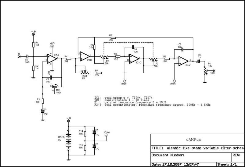
As for Alembic schematics - this would be quite an interesting read. Their svf filter must be in certain aspects somewhat "close" to BBE maximizer process?
(maybe you know of a emg bass-pickup schematic variant ???)
a) observation of emg circuit: it seems that "simmetry" which duncan talks about in it's product blurb refers to this particular emg's topology which is obviously balanced but asymetric (~70k/22n in positive branch and ~30k/22n in negative); lm4250 has noise figure comparable to tl061 @ low bias setting, but fairly low input noise current (wasn't Fender the first one who used that chip - in Musicmans?), another contender could be ua776 which may have a little lower voltage noise but may have more input current noise. All in all, (not really comparable) carvin's solution is imho slightly more intelligent (mc33178 has extremely low input noise current for a bipolar opamp) but sucks ~2 orders of magnitude more current. Yes, I believe Carvin's PU's are "ordinary", they have axes with single-ended preamps as well...
b) In basses, passive humbuckers are usually loaded with either: 2×500k volume pots, 2×250k balance pots + 1×250k volume pot or 2×200k balance pot where volume pot is post-preamp. This means that carvin circuit puts less load to -one- pickup than comparable single-ended solutions. I'm pretty familiar with passive pickup loading effects, have been tinkering with that since late 80's and (repeating again) have a perfectly working solution(s) which work(s) unproportionally good compared to it's monetary value.
c) I dislike "active pickup sound" as much as bartolini "brights" sound. eek.
d) I somewhat like sound of a plain higher-impendance-than-usual fet-input, that's why I'd like an all-fet stage (I'm repeating myself again) ... to keep things simple, -symmetric- (maybe similar to duncan's blurb) and if I decided to use opamps I'd use a guitar-pickup-pimped take on this circuit: http://www.dself.dsl.pipex.com/ampins/balanced/balfig13.gif (which should present a similar load to pickups) ... my fet input stage seems the closest to this idea of a stage that presents a symmetric load to a pickup (and simplicity which == low current consumption in this case) plus I already know how such circuit soudns so this may be a logical starting point for furder pimping and tweaking and comparisons.
Of course, at this time of writing I havent tested it yet (I would like to have a spare "playground" istrument to dig into it freely) plus I'm fully aware that somebody may lurk here with "marketable intentions". When I was gigging, I have pimped my cheap-o stage basses well enough to be majorly disliked by players who invested an order of magnitude more in their instrument(s). Fingers, yes but imo the equation for a good tone is: pasive pu's; coil loading another coil; higher than usual load impendance but passive tone control's impendance stays the same -> into a preamp with higher than usual input impendance (and rfi filtering). Other aspects are personal and playing-style preferences.
As for Alembic schematics - this would be quite an interesting read. Their svf filter must be in certain aspects somewhat "close" to BBE maximizer process?
mr coffee
Well-known member
tv,
I think that sounds like a good starting point. No huge gain to dispose of and much better headroom than a discrete differential stage, no resistors in series with your input source like the Carvin or EMG circuits.
Sounds like you know how to construct a Pi LPF using caps and a ferrite bead to go in front of your inputs. Multiple turns through the bead help. You may want to try a common mode choke in series with the pickup leads. At HF, common mode rejection falls off a lot in electronic circuits due to various mismatches.
You might also consider tying the output of your single-ended preamp to the pickup shell through a resistor pad (inverse of your preamp's gain). Might do as much to reduce noise pickup and add a lot less preamp noise than the differential approach.
I'd like to hear back any measurements you take comparing your current design with the differential op amp version. Especially comparing the preamp signal/noise ratio and comparing the electrostatic noise pickup. Maybe measure it 3 feet from a florescent fixture and a computer monitor.
The Alembic circuit is quite straightforward. A JFET buffer for each coil using a dual JFET with the second JFET as a current source active load feeding into a generic Sallen and Key LPF with feedback to control the Q (switched by a 3-position mini toggle).
http://www.dself.dsl.pipex.com/ampins/balanced/balfig13.gif
I think that sounds like a good starting point. No huge gain to dispose of and much better headroom than a discrete differential stage, no resistors in series with your input source like the Carvin or EMG circuits.
Sounds like you know how to construct a Pi LPF using caps and a ferrite bead to go in front of your inputs. Multiple turns through the bead help. You may want to try a common mode choke in series with the pickup leads. At HF, common mode rejection falls off a lot in electronic circuits due to various mismatches.
You might also consider tying the output of your single-ended preamp to the pickup shell through a resistor pad (inverse of your preamp's gain). Might do as much to reduce noise pickup and add a lot less preamp noise than the differential approach.
I'd like to hear back any measurements you take comparing your current design with the differential op amp version. Especially comparing the preamp signal/noise ratio and comparing the electrostatic noise pickup. Maybe measure it 3 feet from a florescent fixture and a computer monitor.
The Alembic circuit is quite straightforward. A JFET buffer for each coil using a dual JFET with the second JFET as a current source active load feeding into a generic Sallen and Key LPF with feedback to control the Q (switched by a 3-position mini toggle).
Have been thinking about this. Something bifilar I guess for "politically correct behaviour".You may want to try a common mode choke in series with the pickup leads.
Otoh, I got suprisingly good results with a dead-simple single-ended PI (C-R-C) filter that at the same time functioned as a "cable sim". Very succesfully removed the annoying "active sound" even when used with opamp buffers.
Unfortunately, slightly unusable with volume-pot-pre-preamp wiring, esp. with vol-pots without treble-bleed.
Have been scratching my head for a while and wasn't able to decipher that one. I have a vague idea, but could you post a snippet?You might also consider tying the output of your single-ended preamp to the pickup shell through a resistor pad (inverse of your preamp's gain). Might do as much to reduce noise pickup and add a lot less preamp noise than the differential approach.
Did you by any chance mean to generate an attenuated inverted signal from the output and feed the pickup "ground" wire with it? So it will sort-of cancel itself a little bit? Not exactly like in this schematic, but vaguely-sort-of:
http://www.dself.dsl.pipex.com/ampins/balanced/balfig12.gif
(pickup would theoretically go in place of R4, R5/R6 would be used to set the gain ratio, "hot" would be dismissed, and "cold" would be used to set the circuit gain).
Or maybe something similar to this, but used in front of the opamp instead behind it? http://www.dself.dsl.pipex.com/ampins/balanced/balfig5a.gif So the "error correcting" would be injected @ pickup "ground wire" via gain-setting resistor divider into negative opamp input?
Or something entirely completelly different?
@Alembic circuits: there must be a SVF filter circuit in existence somewhere. That one was said to possess "Certain Mojific Powers". Personally, I haven't heard one, but have seen a "knockoff" schematic once on the internet. IIRC it was very similar to BBE enhancement process.
All this will take a bit longer than suspected, I'll have to buy some beaten-up guitar to make it a "testbed". Preferrably something with a removable backplate a-la active basses. Or maybe one of those cheap peaveys - they could become useable axes if pimped up properly ....
Funny thing is that my "expensive" bass with bartolinis, shielded cables, shielded cavity ... and boutique electronic picks up lights and CRT more than my el-cheapos with preamps I designed myself. Must be that I tweaked stuff "by ear" and the buzz & fizz irritated me so I filtered it out subconsciously
=============================
QUESTION @ NOISE EXPERTS:
=============================
How does opamp's noise figure affect this configuration?
http://www.dself.dsl.pipex.com/ampins/balanced/balfig13.gif
I mean - does noise multiply across both stages or does it somewhat cancel?
Reason for asking: low-power dual opamp chips are usually @40nV/sqrtHz or some @25nV/sqrtHz. A "generic"opamp version of the circuit would be much simpler and quicker to produce and reproduce with opamps versus a discrete circuit which would require more attention to detail.
In particular - how would TL062 fare in such config noisewise? How can I calculate that? My gut feeling is that there should be a slight noise cancelation, but I may as well be dead-wrong.
mr coffee
Well-known member
Quote:
You might also consider tying the output of your single-ended preamp to the pickup shell through a resistor pad (inverse of your preamp's gain). Might do as much to reduce noise pickup and add a lot less preamp noise than the differential approach.
Have been scratching my head for a while and wasn't able to decipher that one. I have a vague idea, but could you post a snippet?
Did you by any chance mean to generate an attenuated inverted signal from the output and feed the pickup "ground" wire with it?
Not inverted same polarity. That's why you have to pad it down to unity.
<img src="http://216.77.188.54/coDataImages/p/Groups/207/207065/folders/281193/Thumbnails/2281799Preamp.gif" height="67" width="75">
@Alembic circuits: there must be a SVF filter circuit in
No SVF; Sallen & Key LPF with switch to vary op amp gain. At high Q settings it just sounds like a bandpass response - kinda like a wah. Peaked lowpass response.
Gotta run.
1) forum tag cleanup - MrCoffee's schematic as it should be, presented properly:

2) here's alembic's "filter" preamp - taken from the vast flatlands of teh interwebs, so it may not repraesent TheRealThing:
3) here's bbe maximizer according to NJM2153 data:
http://www.radio-flier.com/PDF%20Files/BBE%20482i.pdf
comparison shows that I was wrong and any similarity in function between bbe and alembic filters is of the visual nature only (if you squint).
----------------------------------------------
Upon meditating on MrCoffee's schematic (Hairy Krishna to everybody !), I can't help but to suggest this preamp topology as a "natural" solution:
(scroll down to "An Alternate Feedback Structure" schematic, you'll see what I mean, R4 just calls "HIT ME!!!")
http://www.ciphersbyritter.com/RADELECT/PREJFET/JFETPRE.HTM
Correct me if I was wrong?? (I know that as-is it has excessive gain, should be trimmed for guitar-use)
----------------------------------------------
I'm soo
( ... picking up on other's work)
What about a simple impedance converter stage, likening to a microphone topology?
Perhaps a JFET DC coupled to an emitter follower like the 'Alice' mics?
I've breadboarded a 'floating' differential JFET imp.converter and it sounded fine. Didn't test voltage variations, just designed it for 9V optimal. No voltage trimmer anywhere on the circuit, and offset or noise was not a hinderance.
my 2cents.
The differential I built was much like the wavebourn circuit. It worked fine with and without input caps, and with / without transformer.
The N-FET-DC-E-Follower topo was from the AARL handbook, but it was very much like an unbalanced 'Alice' mic.
In my low-input-level situation, I don't need a lot of input gain. I just use makeup gain and light gate/compression on the way back out.
The impedance buffer is really all I need here, because it really seems to stabilize (or even enhance) the frequency response. BTW, my input Z is >10kR for my A/D.
Akin to a microphone, I've even gone with a single N-JFET with an optional lift switch on the Source Bypass Cap built to 3-6dB of gain. I can get away with not using an output impedance-lowering stage because it is a line-in impedance.
It really woke up my Les Paul and my Washburn 5-string, traditionally un-hyped instruments.
Heck, even a single BJT wakes up those pickups. Maybe it's simple because the impedance is coming from a P-N junction or a space charge instead of a high-impedance coil attached to a long unbalanced cable.
For basses, I found that using opamps "packs" sound much better that discrete circuits, and bipolar opamps (the ones with PNP input pairs even more so) tend to produce much better midrange character than fet-input opamps - possibly the best use would be on j-j stacked hb pu's. Fet opamps otoh "pack" the sound better.
For guitars, opamps == yuck, imo. Discrete circuits all the way. And while basses (to my ears at least) like input caps, for guitars I think that DC-coupled circuits (like the snippets I posted on pg.1) produce better tone.
ymmv
p.s.: @ single jfet-buffer - I noticed that if you put a lot of effects, pedals etc. in your signal chain, single-jfet buffer can sound better, more natural compared to circuits "hardened" with followers etc.; ymmv again.
skipwave
Well-known member
[quote author="tv"]p.s.: @ single jfet-buffer - I noticed that if you put a lot of effects, pedals etc. in your signal chain, single-jfet buffer can sound better, more natural compared to circuits "hardened" with followers etc.; ymmv again.[/quote]
I've been experimenting with different types of jfet buffers, and I like the single source follower best.
Another example of the fet follower into emitter follower topology is the Country Hick DI.
http://www.diyfactory.com/projects/countryhick/countryhick.htm
I've been experimenting with different types of jfet buffers, and I like the single source follower best.
Another example of the fet follower into emitter follower topology is the Country Hick DI.
http://www.diyfactory.com/projects/countryhick/countryhick.htm
clintrubber
Well-known member
[quote author="tv"]For basses, I found that using opamps "packs" sound much better that discrete circuits, and bipolar opamps (the ones with PNP input pairs even more so) tend to produce much better midrange character than fet-input opamps - possibly the best use would be on j-j stacked hb pu's. Fet opamps otoh "pack" the sound better.[/quote]
Interesting observations and a but surprised I am as well. must admit it haven't done much comparing there as I assumed/decided there wasn't a subject there... I mean, there's so much toneshaping before & after that buffer (I'm not after clean sounds, although no distortion either, but a bit of mild overdrive yes please), so the actual exact taste of a buffer stage would be one of the lesser important contributors there.
Interesting observations and a but surprised I am as well. must admit it haven't done much comparing there as I assumed/decided there wasn't a subject there... I mean, there's so much toneshaping before & after that buffer (I'm not after clean sounds, although no distortion either, but a bit of mild overdrive yes please), so the actual exact taste of a buffer stage would be one of the lesser important contributors there.
[quote author="clintrubber"]
Interesting observations and a but surprised I am as well. must admit it haven't done much comparing there as I assumed/decided there wasn't a subject there... I mean, there's so much toneshaping before & after that buffer (I'm not after clean sounds, although no distortion either, but a bit of mild overdrive yes please), so the actual exact taste of a buffer stage would be one of the lesser important contributors there.[/quote]
What would be your preferred overdrive/tone shaping topology?
Situationally, I am primarily recording.
clintrubber
Well-known member
[quote author="beatpoet"][quote author="clintrubber"]
Interesting observations and a but surprised I am as well. must admit it haven't done much comparing there as I assumed/decided there wasn't a subject there... I mean, there's so much toneshaping before & after that buffer (I'm not after clean sounds, although no distortion either, but a bit of mild overdrive yes please), so the actual exact taste of a buffer stage would be one of the lesser important contributors there.[/quote]
What would be your preferred overdrive/tone shaping topology?[/quote]
After having tried lots of stuff, to my own surprise I'm now more or less satisfied with a TS-type F*lltonish circuit, with the 'asym-diodes',
tweaked RC-values and blending in the dry bass signal.
But obviously the final tone is the result of the complete chain
(playing style, pick, string-type, passive J-bass, tweaked TS-style circuit with blend, tube-pre, BBE, ss-power stages, 8*10" and finally whatever filter-curve my ears add).
But while it's too dry on its own, it still can sound decent when blended in with the rest of the sources.
Bye,
Peter
Interesting observations and a but surprised I am as well. must admit it haven't done much comparing there as I assumed/decided there wasn't a subject there... I mean, there's so much toneshaping before & after that buffer (I'm not after clean sounds, although no distortion either, but a bit of mild overdrive yes please), so the actual exact taste of a buffer stage would be one of the lesser important contributors there.[/quote]
What would be your preferred overdrive/tone shaping topology?[/quote]
After having tried lots of stuff, to my own surprise I'm now more or less satisfied with a TS-type F*lltonish circuit, with the 'asym-diodes',
tweaked RC-values and blending in the dry bass signal.
But obviously the final tone is the result of the complete chain
(playing style, pick, string-type, passive J-bass, tweaked TS-style circuit with blend, tube-pre, BBE, ss-power stages, 8*10" and finally whatever filter-curve my ears add).
Unsurprisingly using just that TS-style circuit before a 'dry recorder' won't give me the same sound - it could have comparable drive, but doesn't give the tone-in-a-room feel.Situationally, I am primarily recording.
But while it's too dry on its own, it still can sound decent when blended in with the rest of the sources.
Bye,
Peter
Similar threads
- Replies
- 2
- Views
- 396
- Replies
- 4
- Views
- 4K