Infos about Mastering Labs ML10 Crossover for Tannoy SRM10B needed

GroupDIY Audio Forum

Help Support GroupDIY Audio Forum:

This site may earn a commission from merchant affiliate links, including eBay, Amazon, and others.
Hi, I'm rather new in this forum. got the pics from Jensenmann and try to draw the circuit after the pics. Will take some time, since this is not my main topic. Wanted to ask, if there are more infos availlable in the meantime?
Figured out the values? Would be greeeeeaaat.

Cheers Ernst
 
Hi,

meanwhile I have been drawing a circuit after the photos I got. For some details I was just guessing, since not all traces could be seen (hidden by the green potentiometer).
These details I've coloured grey in the right part of the picture.
Here you can see the biggest format I could insert. Below there is a link that leads to a bigger sized picture. 
crossover.JPG


Link:
http://picasaweb.google.de/lh/photo/Y_uqCWlDB2b4o8M09gR0ow?feat=directlink

Pucho, would you please be so kind to add the values? And would you mind checking the hidden traces and tell me if my sketch is right or wrong.

Thank you!

Cheers Ernst


lets make some corrections first.... there is only 1 l-pad...  it works for the High frequency driver. then there is a switch  for 9K and above which either makes it work as normal, boost it, and or cuts it depending on switch position....

 
Pucho,

unfortunately I don't really know what you mean, so I ask:
An L-pad is a potentiometer (the green one in my drawig) or is ist the level reducing comination of resistor before the high frequency driver? 

In terms of switch: It seems to be a switch (three positions as ýou mentioned) that has two switching layers. The switch in my sketch is pink. The two layers are SW1a and SW1b. Both are combined in one switch, but I could just draw it as I did. Is this wrong?

Ernst
 
almost forgot in the middle of a mix but will pull those apart once the project finishes and get you real values.... You know I have had good luck getting schematics for repair work from manley lately unfortunately they are usually incomplete in some way but good enough to make repairs happen... Just need a proper serial number. Maybe I could ask for these as well?
 
Pucho,

I'm not really good in drawing and I don't have a dedicated program therefor.
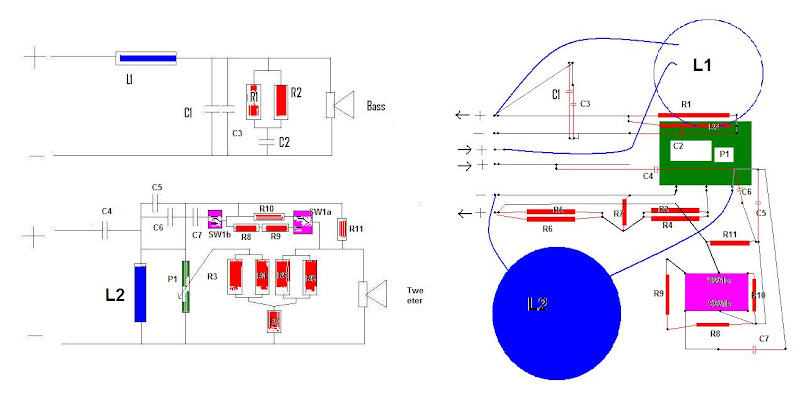
The naming on the left side (schematic) is the same than on the right side of the picture (this is graphically, what I've seen on the photos).

The blue ones are the inductors

L1 for the bass
L2 for the tweeter

The red ones are the resistors

the green P1 is the pot

the pink is the switch with 2 separated layers.

The traces, that I am sure about are black. Two traces, I am not sure about, are grey (just in the right picture).

*So, a very important point is to clarify, if the scematic is right or not right.
*For the values, resistors could be identified via color codes. On the pics the are not really good to identify for me, since colors on photos always differ. To be honest, for some resistors this might be the only way to figure out the values, since one might not be able to measure the resistor only. So it would be great after clarifying the schematic to determine the resistors color code.
*If you cant figure out the inductors, it would help to know the outer and inner diameter, teh thickness of the wire and the thickness of the coil.
* the capacitors should have their values written on themselfes. The values of the small might not be so important if there is no value on.
* the value of the pot would be an important one, but probably difficult to get in case of there is no bagde on it.

Of course, the more info you can get from Manley the better it is. But if we can figure out all of them without further info, why not do it without them. It depends, how far you want to go. It might be necessary to take a soldering iron to get everything we need, or ask again Manley. So we absolutely depend on your kindness! 
Which mighty peace of information is in the documentation you got from them?

Do you need a better or bigger sketch?  A list, containing all partnames? I'll setup a google spreadsheet, in which you can find all the partnames. This might be the easiest way for you to fill in what you figures out.

Cheers Ernst 
 
Pucho,

I started a google spreadsheet with the partslist:

https://spreadsheets.google.com/ccc?key=0Ap56Xc-v9uPHdE1XeFg4UGZFQXhjRjdzdmZZblVBSWc&hl=en

It would be great, if you could type in the known values.

Regards Ernst
 
hey i have some system 10 s and i took a pic on my i phone that i can send,if you pm an email,,
mine are blown,but getting a better crossover network could be a reason to fix them?
 
sorry guys things are slow at me getting to this. I have 2 sets of  mastering lab speakers. one sets has the original tannoy concentric driver and the other set has B&C coaxial speakers. The B&C are a good match IMO.... I will have values soon...  but I do not have an LCR meter so I will have to go about that using resistance.

 
Hi Pucho,

ho hurry from my side :) with speaker that are almost 30 years old :)

An option would be to take down the resistors colorcode. From these most of the resistors should be found out, shouldn't they?

John, as I understood you have a srm 10b ? right. anything special about it?

Cheers Ernst 
 
well at that point it becomes a math problem. If we fill in all the wholes(resistors) and such what's left is the inductors and well with all that other info we could get that.
 
OK, I see, you wrote LCR meter.
Anyway, it will be difficult to figure out the values by measuring, as long as all parts are part of a network, which means, it is not possible to measure these if they were not desoldered at least on one side.  ???

So we have some options:
1) Resistors: Figure out values from colour code - best option if color rings on resistors are good to see.
    Caps: read from label: best option if value is taken down on the cap.
    Inductors: Compare dimensions (outer/ inner diameter / thickness and wire diameter) with inductors from different suppiers, or one can try to build a coil after these measures.
    That would be a quick and dirty "non destructive" option. And the second best at least.

2)  Perfect way would be: Desolder at least one end of each part and measure with LCR meter. Since you have no, this is a problem.
    Well, if there were no way for you to borrow one, an option would be, to put X- over in a parcel and send it to me. I would take  over cost of course! After a few days I'd send it back to you. No costs for you, just you had to trust me. Please take this just as an option. I would understand if this were no option for you. Although it would be simple and less work for you. 

A lot of ways were between option one and two, but to be honest, option one would give the same results as option two.

Please tell me what you think.

Regards Ernst 


3) Is anything of interest in the repairpaper you got from Manley?
 
 
Pucho,

I'm still interested in this thread and would be very happy to have you back here.

I created a google document here:
https://spreadsheets.google.com/ccc?key=0Ap56Xc-v9uPHdE1XeFg4UGZFQXhjRjdzdmZZblVBSWc&hl=en

I added all parts I've drawn in my circuit sketch. I started fillig it with infos I could get out of your pictures.
Regarding Caps: I found out, that the handwritten numbers on the caps are the measure values. I've taken down what I could read.
Regarding resistors: colour code is a good option to figure out values. Would you mind adding colourcodes from the open ones?
Regarding Inductors: Looks like there were a small sticker on the outer side of the coils. Could imagine that it might be possibel to find interesting info there.

Looking  foreward to hearing from you.

Ernst
 
Sorry sir. Things have gotten out of hand lately with a lot of shit... Mostly hard to deal with and tough to swallow but hey life will move on and things will be good again.  I will get back onto it asap...
 
Tungstengruvsten said:
I work at Tannoy....what am I looking for?  ;D

The story I had been told years ago was that when Tannoy switched to the "Gold" series, they changed the crossovers and that the Mastering Lab's version was a copy of the original 10b to retrofit into later speakers.

If possible and you have the time, can you check if there was a design change between the versions and if a second schematic exists?...
 
Has anyone found any new info on these crossovers yet??

I've got a set of srm10b that I'd love to mod.

There's good info already here and it looked like it was going somewhere. Anyone care to continue on this?

 
pucho812 said:
sorry guys things are slow at me getting to this. I have 2 sets of  mastering lab speakers. one sets has the original tannoy concentric driver and the other set has B&C coaxial speakers. The B&C are a good match IMO.... I will have values soon...  but I do not have an LCR meter so I will have to go about that using resistance.

Still VERY curious of the ML10 crossover. Looking to upgrade a pair of Dover, they totally rule, just a little lack of loy end and slight 800htz bump. great speakers
 
since the SRM10 feature the same range of drivers with pepperpot and hard edge surround this crossover schematic that has been discussed quite a lot in the Tannoy newsgroup might be a good starting point .
It is however for the 15" Coax drivers from that era .

http://www.hilberink.nl/codehans/tannoy133.htm
 
Back
Top