Insight into "U47-inspired" with EF12 tube?

GroupDIY Audio Forum

Help Support GroupDIY Audio Forum:

This site may earn a commission from merchant affiliate links, including eBay, Amazon, and others.
OK, how about this?

Screenshot2011-01-22at41739AM.png


Now I might be off-base, but I thought it was good to keep the impedance down in the supply rail so that fluctuations in current didn't cause the power supply to sag, correct?

Would a high resistance in the voltage divider cause the supply to sag under load?  Of course we're dealing in fractions of mA here so it practically probably wouldn't be a big deal, right? 

Anyway, I went with 10K and 8k2, and used a 1K trimmer.  That's a compromise that puts power dissipation at about 1.5W for most settings, which with a 3W trimmer should be fine, right?
 
soapfoot said:
Using a capacitor input filter for the HT supply, given a PT secondary of 160VAC and a current draw of .55mA, after the first capacitor I should have 225.6VDC, and a current draw of 0.34mA.

Is this correct?

No - current doesn't change! That 0.34mA is wrong (I'm guessing you extrapolated that from the rectifier chart I linked to, but that is the AC current in the transformer secondary, not relevant to your DC calculations.)  The current we are concerned with is the known DC current drawn by the tube, 0.55mA).

225.6 is nearly right. (There is 1.4V double-diode drop through the bridge - each diode will drop 0.7V and two are conducting at any one time.) For a secondary voltage of 160VAC, you are going to have a rectified DC of 222V. (158.6 x 1.4)


what's the best way to drop 120 volts to get to the final 105V supply?  High resistor values in the pi filters?  A simple voltage divider or series resistor at the end?  It seems that 360K of total series resistance would drop that much, but I don't know if that's the right way to go.  Something tells me "probably not."

Yes, much higher resistance in the filters.

Your tube wants 0.55mA @ 105V. 

You need a voltage drop of 117V, and you have a current of 0.55mA to make it happen. Ohms Law for this is R=E/I, so 117/0.00055 which is 212727, or approx 213k.

Thus you are looking for a series of preferred values that make up close to 213k in total (maybe a little less to allow range for the trimmer, but you don't want to shunt too much current to ground).


The MK7 PSU is indeed a great helper. Can you spot the mistake in the marked voltages on the HT side? What should it say?  :)

 
MagnetoSound said:
No - current doesn't change! That 0.34mA is wrong (I'm guessing you extrapolated that from the rectifier chart I linked to, but that is the AC current in the transformer secondary, not relevant to your DC calculations.)  The current we are concerned with is the known DC current drawn by the tube, 0.55mA).

225.6 is nearly right. (There is 1.4V double-diode drop through the bridge - each diode will drop 0.7V and two are conducting at any one time.) For a secondary voltage of 160VAC, you are going to have a rectified DC of 222V. (158.6 x 1.4)

You're right, that's exactly the mistake I made.  I'll make the necessary adjustments.  Thank you.

However, some of my voltages come from simulations I ran using PSU Designer II.  I downloaded a Windows emulator and this program and ran simulations on my design.  It was really instructive.


Yes, much higher resistance in the filters.

Your tube wants 0.55mA @ 105V.  

You need a voltage drop of 117V, and you have a current of 0.55mA to make it happen. Ohms Law for this is R=E/I, so 117/0.00055 which is 212727, or approx 213k.

Thus you are looking for a series of preferred values that make up close to 213k in total (maybe a little less to allow range for the trimmer, but you don't want to shunt too much current to ground).

OK.  So let me ask you this question-- actually a series of questions.  Just so that I can learn...

1) What is the disadvantage to "shunt[ing] too much current to ground" besides needing components with high power handling capability?  What are the problems and potential pitfalls to that design?

2) Doesn't the amount of resistance in the filters increase the voltage drop across those resistors as more current is drawn?

3) Wont the .55mA of current draw vary somewhat depending upon what is happening in the tube-- how much the tube is conducting?  This is the case in other tube circuits I've worked on.

4) If (2) and (3) are true, then won't that cause the voltages to "sag" dynamically under load... 'browning out' the voltage as the load draws more current?

5) If (4) is true, wouldn't that cause a type of distortion especially when the tube is conducting near its maximum, made worse as resistance in the B+ string is increased?


Just trying to get a handle on this.  Thanks.

--brad
 
What if I just tried to find a transformer that had an 80V secondary or 100V secondary?  Then I wouldn't have to drop so much voltage.  I've been looking all morning but a transformer with an 80V and 12V winding doesn't seem to be a "standard" item.
 
Wont the .55mA of current draw vary somewhat depending upon what is happening in the tube-- how much the tube is conducting?  This is the case in other tube circuits I've worked on.

It will vary somewhat, but how much? The tube is biased to an operating point which sets plate current at a point somewhere between fully on and fully off. Because we are dealing with really tiny signals, it can be biased fairly close to cutoff. At the point we've chosen the tube draws 0.55mA. From there it is modulated by the AC signal on the grid. As the grid goes positive, the current increases and the voltage on the plate drops. As the grid goes negative, the current drops and the voltage increases. But the signal at the plate is in the range of a few tiny millivolts - not enough to make a real difference across a resistance designed to drop more than a hundred volts.

Doesn't the amount of resistance in the filters increase the voltage drop across those resistors as more current is drawn?

Yes, that's how Ohm's Law works. You need to drop 117V - that's quite a lot, so you need enough series resistance, otherwise you end up wasting heat in a high-wattage shunt for no practical gain. Granted, the supply will be stiffer - but this is not a power amp, it is a tiny mic amp with no significant loading on it.

What is the disadvantage to "shunt[ing] too much current to ground" besides needing components with high power handling capability?  What are the problems and potential pitfalls to that design?

You try to avoid wasting power. Your mic is asking for a tiny amount of power to make it work, not quite 60mW! Any extra power that you pull through shunt resistance is not contributing anything except extra heat inside the PSU. Not a problem and it might not bother you, but too much is not good practice.

 
soapfoot said:
What if I just tried to find a transformer that had an 80V secondary or 100V secondary?  Then I wouldn't have to drop so much voltage.  I've been looking all morning but a transformer with an 80V and 12V winding doesn't seem to be a "standard" item.

You'd probably find one with a 120V sec without searching too hard. You can always use a separate transformer for the filament supply. Or just use what you have and adjust the resistors.

 
Thanks for your answers and explanations.  It makes sense to me. 

I haven't purchased a transformer yet.  I thought about doing a separate xformer for the filament supply, as you suggested and may indeed go that route.  5 coils in one PSU!  One heavy beast.

I saw this on Edcor's site:

EDCOR charges a $40.00 design and setup fee for quantities less than 10 pieces. We have a large database of designs going back over 30 years and if we already have the transformer on file then the design and setup fee is waived.

I sent them a note asking if they had anything similar/close to what I needed.  We'll see what they say.
 
No luck on the Edcor front.

Now I'm deciding... do I waste a bunch of extra power with the 160V PT, or do I make my PSU heavier and more expensive than it needs to be?
 
I found this transformer, Hammond model number 262B24.

It has a 120V secondary at 27mA (should be plenty for the .55mA B+ supply), and DUAL 12V secondaries at .2A apiece.  Am I correct that I can connect those dual 12V secondaries in parallel for double the current rating, having 12V @ .4A?

If so, this might be a good transformer for my needs.

OR I might just ante up and have Edcor make me a custom one, which if my guess is right would probably run around 65-70 bucks.  The Hammond would probably run around 27 bucks.

http://angela.com/hammondlowpowerbiaspowertransformer262b24.aspx

Hmm.
 
That one looks fine.

I'm going to stop here. All you need is in this thread, zebra50's points about the merits of adapting a proven design are extremely worthwhile (that's how we all learned it), and you have what you need to do that. I strongly suggest you go back and re-read everything that has been posted here regarding Ohms Law and rectifier relationships at least once and thoroughly digest it before you begin.

Good luck!  :)

 
I will do that.

Thanks for all your help.  I've gotten some help from some other sources, too, and it's all coming into focus.  I don't know that there's much left except for me to review and adjust my designs, order some parts and start breadboarding. 

 
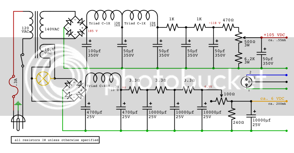
Antique Electronics Supply has a transformer with a 140V secondary and a 10.5 @ 2A secondary for 20 bucks.  Looks nice.  I ran some simulations in PSU Designer II, tweaked some values, and this is what I have right now:

Screenshot2011-01-23at23314AM.png
 
Just so I'm following you, it's this transformer right?

P-T292

Catalog Page 36

Transformer, Power

    * 120 V primary

    * Secondary 1 - 140 V, 100mA
    * Secondary 2 - 28 V, 20mA
    * Secondary 3 - 10.5 V, 2A


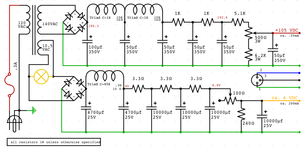
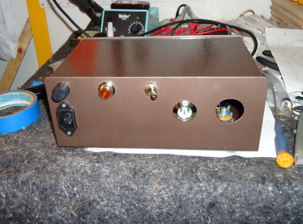
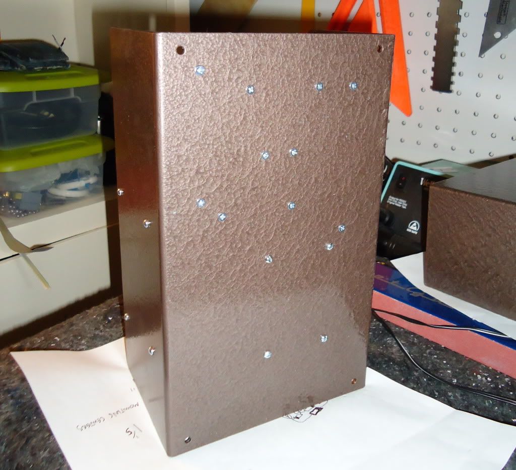
OK!  I completed this PSU.  It came out great so far.  This weekend I'll go pick up an oscilloscope to make sure everything is quiet and ripple-free, but for now I'm optimistic.  For the most part, all my math was correct thanks to the help of people on this thread/forum.  I had to change one resistor from 5k1 to 470R to get the right adjustment range on the B+ side.

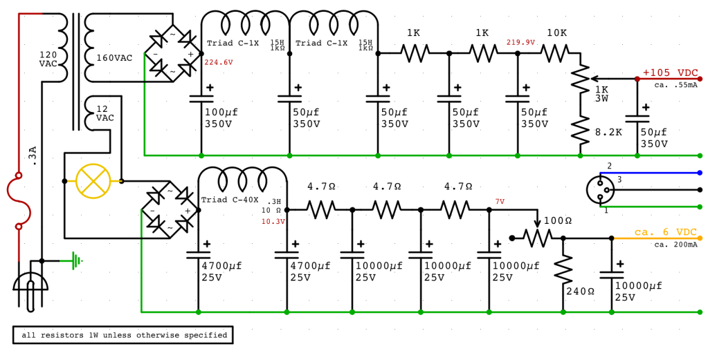
Here's my final schematic (unless there are problems with ripple that necessitate further changes). 

Screenshot2011-03-01at42222PM.png


On the filament side, my adjustment range with the pot, while hooked up to an actual filament of an EF12 tube, is 3.5V to 6.6V.  This seems like a pretty good range... there's some 'excess' on the ends but the range is narrow enough that I can fine-tune the sweet spot between 5 and 6.3V in the middle.  It's not "***** proof," but there's nothing there that's too dangerously far out of range, either, for short-term trimming.

On the B+ side, assuming a current of .55mA and a target voltage of 105V, I estimated a 200K resistor to simulate the load of the mic.  With a 200K load resistor, my adjustment range on the B+ side is between about 101V and 110V.  This seems like a pretty safe, narrow range around 105V that will allow for very precise fine-tuning.

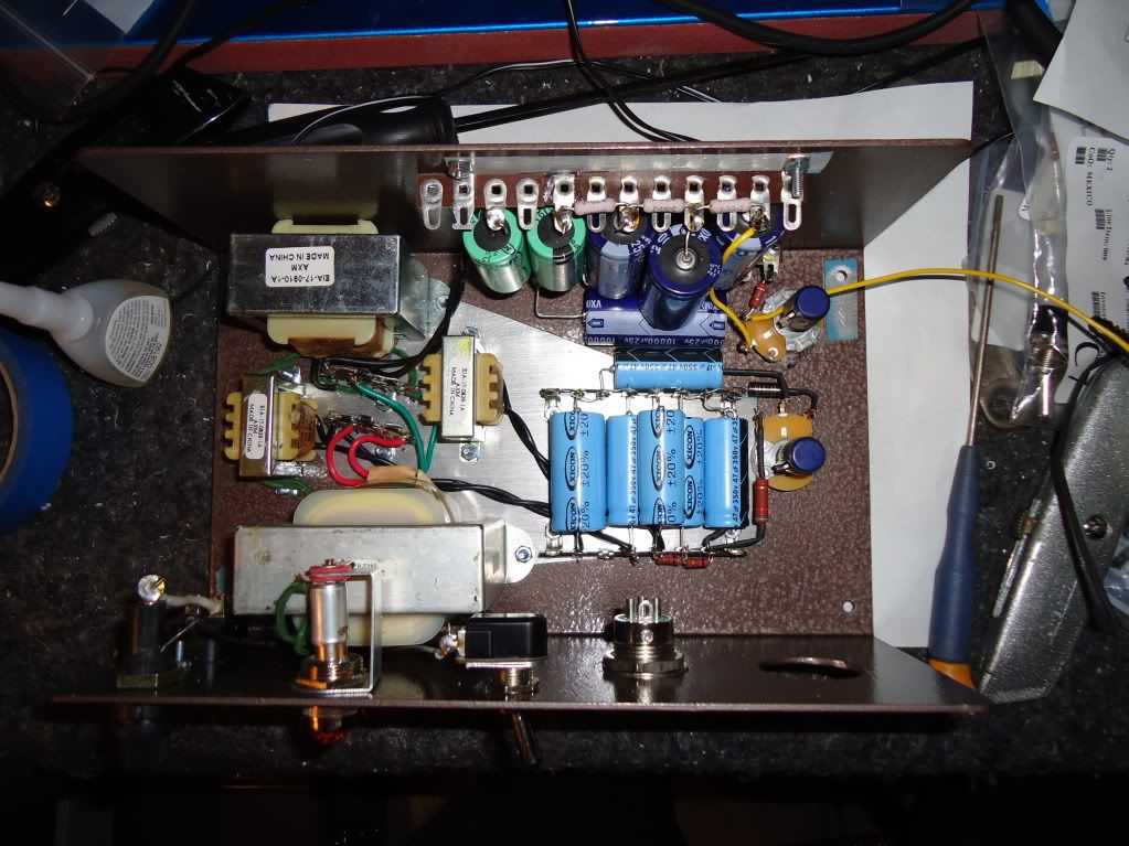
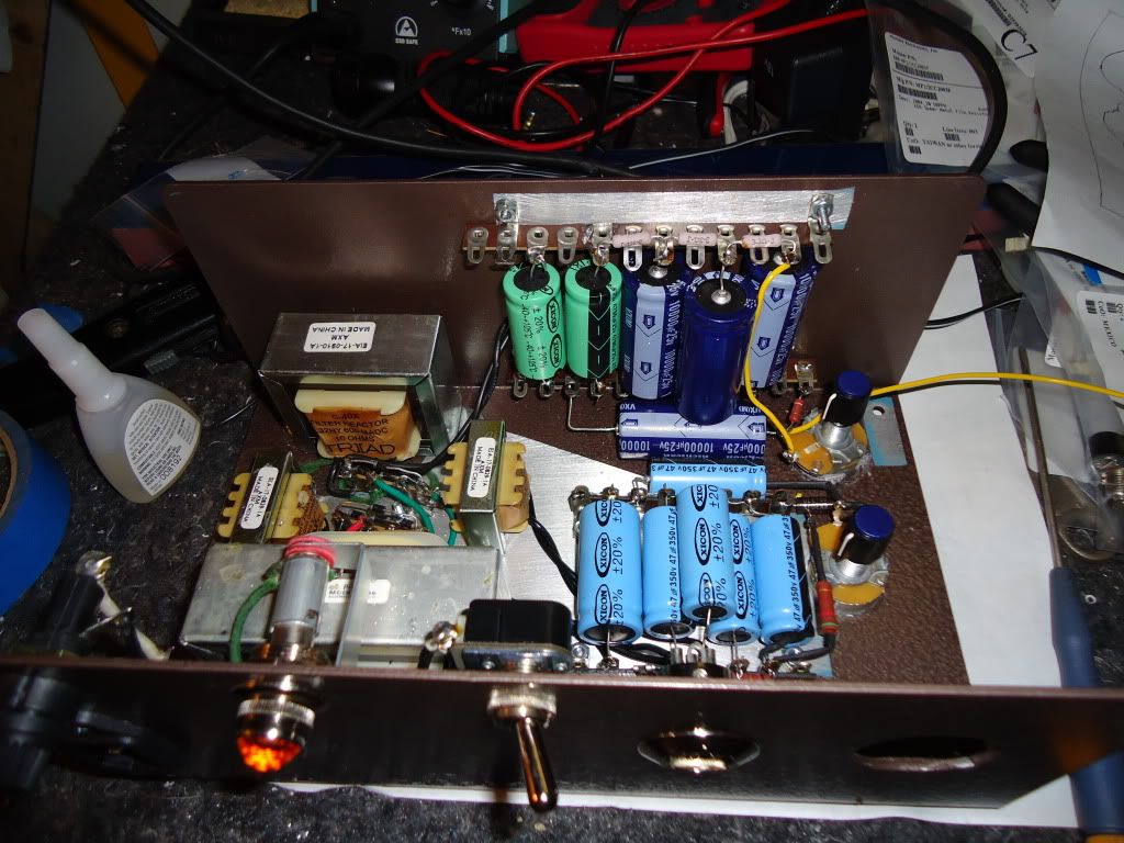
I went total overkill on the build.  I even added knobs on the internal pots... what the hell, why not... I had some extra-ugly ones laying around.  I still am waiting on a 7-pin Binder connector to use for the tube mic cable connection.  Here are some pics:

DSC00615.jpg

DSC00617.jpg

DSC00621.jpg

DSC00606.jpg

 
Your voltage adjustment range is a bit short for my taste. For instance, the B+ is a little short from +/-5%. Now what happens if your mic ends up in a place were AC mains is 10% higher or lower than whatever it is now?

Axel
 
true, and duly noted.  I'll keep an eye on that for the future.  I was trying to strike a balance between adjustability, fine control of adjustability, and not having anything so far outside the range as to be immediately dangerous for the mic should it get bumped out of adjustment or whatever.  But your point is very well taken.
 
Just for an update: after discussing this with lots of bright people, I've chickened out on the EF12 and will be using an EF800 instead.  After these discussions, I was wanting to use a higher plate voltage with the EF12 than my supply was designed for, and rather than starting all over with a different supply, I just decided to use an alternate tube.  At first I wanted to run the EF14, but the heater current used by that tube would've dropped my heater voltage too low, and there was no easy way to modify my supply without this short of regulation, which would've been a big re-design.  The EF800, with its heater current draw of about 275mA (compared to 200mA for the EF12 and 470mA for the EF14) seemed to be a good choice-- and Oliver Archut already has a schematic for a 47-inspired mic using that tube.

Once I get the build underway, I will start a more appropriately titled thread.  Thanks everyone for your input here.  I've learned a lot that has helped me throughout this process already.


Please note, that for a power supply stabilized like this, it's VERY important to have the microphone plugged in BEFORE turning on the power.

Otherwize high voltage will build up in the last reservoir capacitor and discharge with a shock when you plug in your mic...

Jakob E.
 

Latest posts

Back
Top