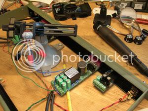
Actually i might be able to take some pics. Nothing drastically different to what we've seen so far however.
anyway, onwards with the questions and learning..................................................................................................................................................................................................
I've been looking over the schematic as much as possible, just to try and understand the workings a bit more. I tend to struggle with schems seperating whats the audio singal path and whats the rest, but I think the Baby A is so nice and simple even I get it. :shock:
So just for example with the caps, would I be right in saying that the only caps that the audio signal go's through are CZ
(if used), CL, the 47pf and the 470uf's before output pin one, and also pin three?
My main reason for asking is, that in my hunt for good quality caps
(rubycon,nchicon etc) in the 470uf rating, i've found that a lot of em are 12.5m diameter, which makes for a bit of a squeeze and caps kinda hanging off the side of the board, where as quite a few general purpose panasonics are 10mm. Now I don't want to start a what cap is best kinda thing here coz there's so many threads on that already, but I'm more interseted in learning what the caps actually are doing in this curcuit. I understand that Low ESR is better, etc, but I could buy some really expensive caps that may not effect the signal as much as my ignorance would lead me to beleive. Does that make sense?
I think the Nichion HE series has a 470uf/50v thats 10mmx16mm, if thats any help to anyone else sourcing their own parts like me. There is also another on thats 16mmx15mm which wont be useable. Mouser lets you choose between the two, but i've found that RS only has one on offer and they dont't seem to tell you what dimensions you're getting. I could be readin it wrong however. Anyway, I hope that helps anyone. :grin:
Greg said something earlier about the 47pf's being for high frequency stability. And the 0.1uf you've already explained to me. :thumb:
The loading thing is something I know we'll get to later.
The other thing i was goin to ask was, about the connection between pins 7 & 4 on the IC, as in the JLM1:4,99v shem. Now I'm goin to be using a 1/4" jack output rather than a quasi balanced xlr, (
due to a chassi that I scored for free with jack outouts already fitted, and that my inputs into my computa are mostly rca's)
Can i get away without the jumper as there's no pin3 for me, or do i still need the jumper anyway? My guess would be no jumper........ .....
Well, hopefully i can find my flatty's camera and put up some pics of the build, albiet mid process for all to see.
I will be back

Steve


