JLM Baby Animal

GroupDIY Audio Forum

Help Support GroupDIY Audio Forum:

This site may earn a commission from merchant affiliate links, including eBay, Amazon, and others.
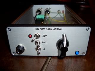
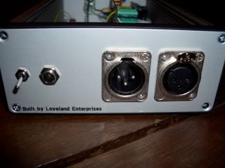
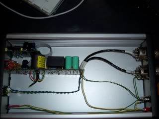
Here's a BA i built for a friend, 99V JLM 1:4 transformer.

CIMG0751.jpg


CIMG0761-1.jpg


CIMG0762-1.jpg


Great pre's and service for JLM. Am about to make another four for myself.

BL
 
i was wondering if some has a front panel express file with the holes marked out for a baby animal preamp that they would be willing to share.

I suck at designing stuff in front panel designer, and would greatly benefit from something to use as a starting point for my frontpanel.

If not, i will try to do it myself when i get the time and would of course share my work with anyone who might need it to save some time.

Thanks!
/J
 
Good idea, if you look closely at the front panel above you'll see a slight gap above the pad switch, oops!!! Hopefully i'll have some time come next holidays and do something similar.
 
[quote author="Jonkan"]i was wondering if some has a front panel express file with the holes marked out for a baby animal preamp that they would be willing to share.[/quote]Mine was a ruler and pencil job I'm afraid, otherwise I would've been happy to share.

Cheers

Nick
 
[quote author="Jonkan"]i was wondering if some has a front panel express file with the holes marked out for a baby animal preamp that they would be willing to share.

I suck at designing stuff in front panel designer, and would greatly benefit from something to use as a starting point for my frontpanel.

If not, i will try to do it myself when i get the time and would of course share my work with anyone who might need it to save some time.

Thanks!
/J[/quote]

Yes, I have a starter "boiler plate" that I've adapted from my 1272 project which used the JLM go between and DI boards. The spacing between the switches on the baby animal and the go-between boards is probably close if not dead on.
Anyway, for what it's worth -- here it is:
http://img.indigom.net/fpd/

The enclosure holes are meant to match the aluminum chassis from USA based par-metal.

Be sure to use a caliper and measure everything 3 times!! I have so many expensive mistakes in front panel desiging.

cheers~
-Jay
 
Hello,

I need to put together 4 ch. of BAs with Cinemag CMMI-8PCA input iron,
Fabios 2520 opamps and his API 312 output iron. Has anyone of you built this one yet?

I am looking for the info about which components to use or to left out on the
BA PCB and how to connect the Fabios output ironfor higher ratio.
 
You're basically just building a 312 circuit. I would refer to the API 312 schematic, and stuff the components as such. And of course Joe's schematic and PCB layout.

What ratio do you want to wire the output? Higher than 1:2 will make the opamp see a very low impendence assuming a 600 ohm load. What is your motivation for the higher ratio?
 
Hi guys it's been like 2 months since my last post. i've been working a litle 2 jobs....Now back to business. Here we go 4 channels of Baby animals.
First 2 channels use OEP, Hybrid and Cinemag output. very very nice on it's own. 2nd pair are Yamaha Input trafo, Melcor 1731 no output. they are very different from the rest altough no my first choice. thik i'm gonna change them ( Input trafo) someday.

normal_P3240577.JPG

normal_P3240575.JPG

normal_P3240576.JPG

normal_P3240579.JPG
[/img]
 
Thanks everyone for putting up so many good examples of the Baby Animals :grin: :cool:

I have had a lot of questions about doing 312 on the BA PCB which is easy. 2622 input transformer or modern equivalent like Cinemag CMMI-8PCA. RL = Not Fitted, RZ = 5k1 CZ = 220pF. 2503 or JLM111DC output transformer wired as 1:2. A 2520 opamp and change the 47pF cap to 220pF.

You could also go and change the negative feedback resistor from 10k to 20k and the RG from 68R to 200R and the 10k rev log pot to 20k rev log and the 470uF cap to 250uF and the 47pF cap to 120pF. But these changes will make no tone difference except for 120pF cap. So it is best to leave the circuit as it is and only change the 47pF to 220pF so the bandwidth is set the same as the 312 was.

Finally Baby Animal Dual (BAD) PCB and kits are now up on the JLM website on the Baby Animal Page here http://www.jlmaudio.com/Baby_Animal_Mic_Pre.htm

BADpcb800.jpg


BAD can do 80dB of gain with ease and because of the 2 gain stages can have a Passive EQ or opto compressor or output level control inserted into the middle of it.

More new kits can be found on the JLM forum.
http://jlmaudio.com/forum/viewforum.php?f=2

Thanks
 
I just checked out the forum, and all the new kits coming up.

Jesus Joe, you're killing me here!

I guess i have to sell one of my kidneys or something, because you are putting out so many cool kits that i want to build, but dont have any money for. I just have alot of spare time right now.

Very nice!!

Will the AD converter be available as a kit too? What ratio are the transformers used btw?

/J
 
Damn you Joe!
Now I'm almost thinking of selling my precious BA's to a friend to get a pair of duals. :wink:
 
I almost fully soldered my BA (w/ 2604 & JLM-14, only the JLM-14 and the Pots are missing) but now I have a question regarding the JLM-14:

As the whole PCB is plated thru and the holes for the screws for the JLM-14 are connected to ground:

Do I have to use proper screws (plastic ones for isolation) or can I use the black screws which were in the kit?

There were two plastic things which looked like they suit the holes and would be able to do the 1 mm space thing but unfortunately they didn't suit.
 
I just checked out the forum, and all the new kits coming up.

Jesus Joe, you're killing me here!
:grin: :cool:

Will the AD converter be available as a kit too? What ratio are the transformers used btw?
The A/D is a 24bit 44.1/48khz card with int/ext word clock in and word clock out that can be bought for a couple of hundred dollars and runs on +/-5v. It has a full wavefront chip set on it including the Optical to 2 x 4 digital output chip which is only used for its wordclock input. Has bad opamps running on the +/-5v rails. We bypassed all audio parts on the PCB so only the +5v and on board 3.3v rail is needed to run the 4 x CS5333 A/D chips and used 8 x JLM14 wired as 4:1 step down transformers into the A/D chip directly with the right low impedance and padding values and this changed the card from a horrible harsh sounding card to very smooth and fat sounding with more in common with a good tape machine than a A/D.
It is on the JLM forum to see what demand there is to turn it into a easy to make kit.

Do I have to use proper screws (plastic ones for isolation) or can I use the black screws which were in the kit?
There were two plastic things which looked like they suit the wholes and would be able to do the 1 mm space thing but unfortunately they didn't suit.
Cut the tube part off the supplied white insulators with a sharp knife to make them into flat washers. Then use the 2 black screws are used to hold the JLM14 to the PCB with the white washers in between the JLM14 and the top of the PCB.
 
What's the difference between the JLM14 & the OEP262A3C

I have to order a pair of Baby Animals with 99v & DI
but still don't know if choose the JLM14 or OEP262A3C

Thanks
 

Latest posts

Back
Top