I just did this again.....
Put your DMM in current measuring mode. Take a Jfet, short gate and source together, and connect to negative terminal of a 9V battery. Connect one DMM probe to the drain, the other to the positive 9V battery terminal. You should be able to read the IDSS on the meter.
If your meter can't measure current, then put a 10 ohm resistor (measure it first!) between the drain and the positive battery terminal, then read the voltage drop across the resistor and divide the voltage by the resistance you measured.
[/quote
but put source & gate round the other way ...... got same measurements kinda supprting that it may not matter which way round gate & source are.... but can that really be true....why have a gate & a source if so ..... but yeah in my circuit it didnt seem to make a difference ......
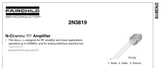
And now the gate might not be middle leg nooooo .....
I had two packeds of FETS that I have lost track of where they came from ....at least one cmae from Farnell recently ...... other prob Farnell too but earlier date ..... I have two FETs I found in my junk box unused one looks much older was saving it in case it had special vintage pixy dust on it ..... but I think its just moldy from being in the shed for 20 years...
Got fed up with the KM last night & had play with Oktava 012 circuit sounds great was tweaking bias trimmer when little bit of back ground noise dissappeared completly its totally silent , I love that circuit ....
cheers


") ..... does removing C6 0.1u cap upset the voltage at R1 R8 node....... So a cheap digital meter would NOT show 46V at R1 R8 not anyway.... it would upset the circuit..... with no C6 my meter reads 8V, not saying thats right...with the dodgy C6 ( explain in mo) the R1 R6 node read 46mv by chance...... back further in this thread I reported that it read 46V I wonder in my haste if it back then read 46mv.....
..... does removing C6 0.1u cap upset the voltage at R1 R8 node....... So a cheap digital meter would NOT show 46V at R1 R8 not anyway.... it would upset the circuit..... with no C6 my meter reads 8V, not saying thats right...with the dodgy C6 ( explain in mo) the R1 R6 node read 46mv by chance...... back further in this thread I reported that it read 46V I wonder in my haste if it back then read 46mv.....