You are using an out of date browser. It may not display this or other websites correctly.
You should upgrade or use an alternative browser.
You should upgrade or use an alternative browser.
KM84 DIY Body & PCB kit – CLOSED
- Thread starter Banzai
- Start date
Help Support GroupDIY Audio Forum:
This site may earn a commission from merchant affiliate
links, including eBay, Amazon, and others.
Thanks for the info, and for all of the work.. Cheers!Banzai said:Sorry guys for the slight delay – finished packing everything last night, all goes out on Monday (guaranteed). Will provide tracking asap.
Thanks to everyone for your patience!
Max51
Member
Well received ! Thanks !
indraperkasa
Member
just got my tracking, thank you banzai!
TwentyTrees
Well-known member
Kits arrived today - looking great, very smart and great packaging! Now to investigate getting the bodies powdercoated locally...
Thanks for all your work on this gents!
Andy
Thanks for all your work on this gents!
Andy
TillM
Well-known member
everything arrived today !
thank you very much!
thank you very much!
Jim50hertz
Well-known member
Mines arrived today. Look great. Thanks Mike
TwentyTrees said:Kits arrived today - looking great, very smart and great packaging! Now to investigate getting the bodies powdercoated locally...
Thanks for all your work on this gents!
Andy
Another easy option is to polish the brass. Could come out really well.
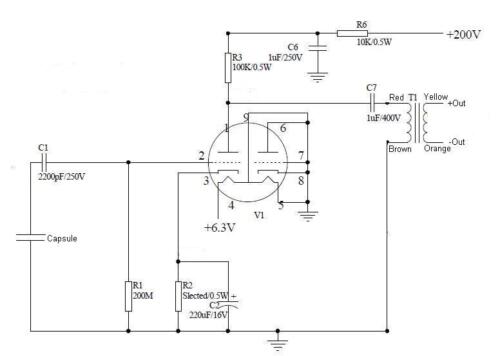
I built 3 KM84's--2 with the Haufe Group Buy transformers. When following the wiring diagram shown on Page 4 of the of the Haufe BV107 Group Buy thread, the microphones are Pin 3 = High; said another way, positive air pressure at the capsule yields a waveform that begins negative. In my world, and the world of nearly all professional audio, this is not a good thing.
This could easily be avoided by swapping the orientation of the white and blue wires on the output side. I have to run out the door, but will try to elaborate when I get back.
=======================================================
After talking to someone more knowledgable than me in interpreting the Haufe transformer diagram, I now 'get' that the 'positive pressure' side of the Haufe primary is the Black wire and the 'positive pressure' side of the secondary is the White wire. So my note (above) is still a warning, but a warning not to interpret the transformer diagram the way I originally did.
adeptusmajor
Well-known member
- Joined
- Mar 17, 2009
- Messages
- 211
Kits arrived in Virginia, they look great!
Any tips for painting/powder coating the body without screwing up the mesh behind the slots in the top?
Any tips for painting/powder coating the body without screwing up the mesh behind the slots in the top?
Potato Cakes
Well-known member
I believe the mesh is easily removed. So do that. If the new bodies have the mesh soldered in you can just desolder it and then remove it.
Thanks!
Paul
Thanks!
Paul
Jim50hertz
Well-known member
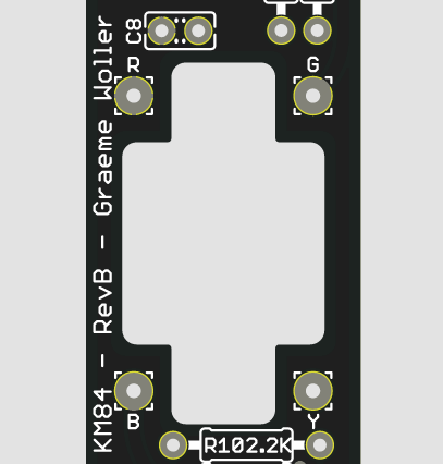
Banzai said:Anyone using the Cinemag 5722, just follow the markings on the board:
R - Red
G - Green
B - Blue
Y - Yellow
That is true if you're using the stock version of the CM5722, where you have to connect the center taps yourself.
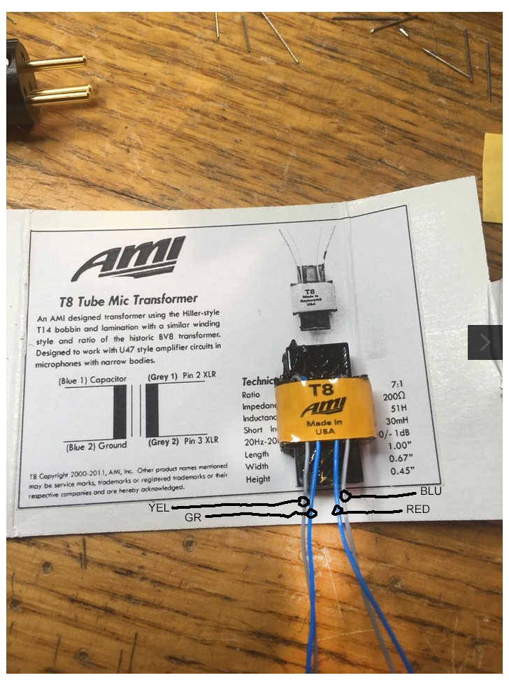
But David from Cinemag offered me the internally hooked up version where the colors are vastly different. If I had read his description more carefully it would have saved me a lot of trouble. Brown/Red is primary - Orange/Yellow is secondary and there are only four wires.
The letters on the board correspond to the following wire colours on the transformer:
G = Brown
R = Red
B = Orange
Y = Yellow
There are no green or blue wires on this version. Keep that in mind!
BTW: thanks Mike for the kit - it's a great sounding mic!
Similar threads
- Replies
- 7
- Views
- 2K
- Replies
- 27
- Views
- 9K
- Replies
- 22
- Views
- 16K


