LA-4A adjustment procedure, and general questions

GroupDIY Audio Forum

Help Support GroupDIY Audio Forum:

This site may earn a commission from merchant affiliate links, including eBay, Amazon, and others.

jhaible

Well-known member
Joined
Jun 24, 2004
Messages
530
Location
Germany
I just looked a little closer at the LA-4A schematics yesterday, and was surprised by some advanced features compared to the LA-2A.

First, I'd like to know how the trimmers should be adjusted, and select on test components should be chosen.

Second, con anybody confirm what vactrols they used? (I presume
VTL5C3 or something of that kind, but I'm not sure.)

Third, I was surprised to see a mix of feedback and feedforward oparation implemented here! (1M resistor from before the GR voltage divider, and 2k2 resistor from buffered attenuated signal) Any background information about this?

Thanks,

JH.
 
[quote author="gyraf"]Hi JH,

Throw us a link to the schematic - that will ease the discussion/dissection..

Jakob E.[/quote]

Jakob, you're right. Here it is:

http://www.waltzingbear.com/Schematics/Urei/LA_4A.htm

JH.
 
> I was surprised to see a mix of feedback and feedforward oparation implemented here! (1M resistor from before the GR voltage divider, and 2k2 resistor from buffered attenuated signal)

LA-2 has the same thing, wired a little different.

In a plain feedback limiter, at very high GR the error signal becomes small compared to the LED current. Made worse because the LDR is going into saturation (its minimum resistance). So the output level starts rising again. With the warped response-law of an LDR, feed-forward can't give an exact limiting action, but a little feed-forward extends the flat-output range a few dB higher.

As for how you -trim- an LA-4: find a manual. R4 and R51 are obvious, but R34 is funky, and R49 probably needs a good dB meter and a best-fit approximate setting. R57 needs a specification of threshold level and the amount of GR they define to be "threshold".
 
If you are thinking about building one:
I made one a few months before, with a What compressor in one box, but wasn't really pleased by it's sound. So last week i desided to throw it out and put a second What-compressor in that same enclosure. Now I
'm happy with it.
For me the What compressor is the better compressor compared to the LA-4A.
 
[quote author="Michael Krusch"]If you are thinking about building one:
I made one a few months before, with a What compressor in one box, but wasn't really pleased by it's sound. So last week i desided to throw it out and put a second What-compressor in that same enclosure. Now I
'm happy with it.
For me the What compressor is the better compressor compared to the LA-4A.[/quote]

Thanks for the warning!

I don't plan to build it exactly. I would never invest in that amount of hardware, big enclosure, big VU meter etc, and then put in 4136 opamps. Or *any* opamps, crying fo an input overload LED, for that matter.

The reason why I'm starting to collect information is this:
I'm quite happy with my (slightly changed) LA-2A clone. Now I plan to build a preamp and equalizer, with a compressor/limiter included. I think this must be an opto, because I like the LA-2A. I also think this might be easier with a LED/LDR combination instead of that Electroluminiscence stuff. So the idea is to use something like a LA4A sidechain, and an input transformer instead of the stupid opamp circuit, a better signal amplifier, either tube or discrete transistor.

JH.
 
[quote author="PRR"]> I was surprised to see a mix of feedback and feedforward oparation implemented here! (1M resistor from before the GR voltage divider, and 2k2 resistor from buffered attenuated signal)

LA-2 has the same thing, wired a little different.
[/quote]

Oh yes, now that you say it, I see it as well.

I've played a little with different ratios between the feedback and feedforward resistior in simulation, and it's clearly visible how the compression courve is bent towards infinity, but only for some small range.
(I've simulated this with a VTL5C3 model for the vactrol, and with the trimpots in mid position. But in fact I don't even know which Vactrol was used in the LA4A - I just think I have read 5C3 somewhere.)

JH.
 
[quote author="Kev"]http://voyager.celestial.com.au/~rosswood/data/images/LA-4%20User%20Manual.PDF

:cool:

219K PDF[/quote]

Thank you!

That will answer a lot of questions.

JH.
 
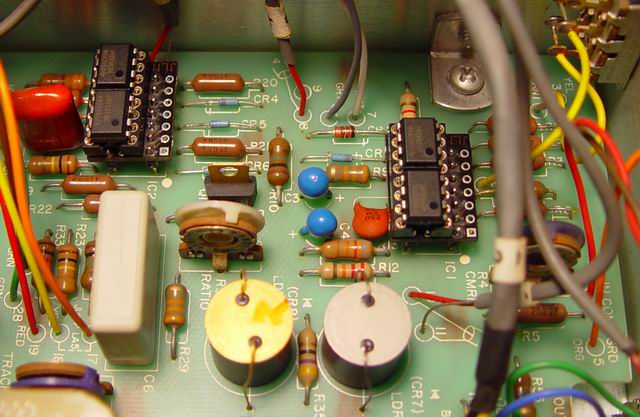
The optos in the LA4 are normal Red LED's mounted on the PCB in a small piece of black plastic tube with a LDR face down on top of them. The LDR is similar looking to the ones in LA2A T4B's. They can be seen at the bottom of this photo. We make adaptors to change the 4136 opamps to either Dual TL072, TL074 for side chain or dual NE5532 or LM837 for audio path. As the 4136 opamps have serious slew distortion.

LA4%20mod%201.jpg


Joe

www.jlmaudio.com
 
[quote author="JLM Audio"]The optos in the LA4 are normal Red LED's mounted on the PCB in a small piece of black plastic tube with a LDR face down on top of them. The LDR is similar looking to the ones in LA2A T4B's. They can be seen at the bottom of this photo. [/quote]

Thank you! (Another surprise - I really had expected some ready-made
Vactol in there ...)

JH.
 

Latest posts

Back
Top