LA2A Build - Finally Works!

GroupDIY Audio Forum

Help Support GroupDIY Audio Forum:

This site may earn a commission from merchant affiliate links, including eBay, Amazon, and others.

airtech

Well-known member
Joined
Jul 19, 2005
Messages
79
Location
Long Beach, California
I don't post a lot here, but was wondering if I could get some advice on my LA2A that I'm rebuilding.
I'll send some pictures later.  A little history, I built a couple of LA2A's based on the Jahnsen book back
about 5 years ago.  One worked, the other didn't.  Check and rechecked.  Swapped tubes and also t4b's.
I'm using his layout, point to point, with ha100x's and a24's for the transformers.

Here's a link to some pictures of the unit:  http://s907.photobucket.com/albums/ac271/airtech101/?albumview=slideshow

My Problem:

After I power it up, no explosions, the meter works fine.  I ran some audio into it and the meter responds.
First thing I noticed is that the gain knob on the left, when all the way off, still lets audio through.  When
I turn it up about a quarter turn the meter slams to the right.  When I turn the right reduction knob, around
a quarter as well, distortion/crackling is audible.  So I checked the voltages against Jahnsen's Voltage Chart.

Here's what I got:

12ax7#1 - pin1-144volts, pin3-1.17volts, pin6-150volts, pin8-1.28volts
12bh7    - pin1-124volts, pin3-4.69volts, pin6-276volts, pin8-130volts
12ax7#2 - pin1-111volts, pin3-tohardtogetto, pin6-111volts, pin8-0.93volts
6hg5      - pin2-50volts, pin5-330volts, pin6325volts

The voltage on the 6hg5 is way high on all pins and the other voltage on the other tubes are approx. 25% more
than whats in the book voltage chart.  Any ideas on what could be happening?  I've checked and rechecked the
wiring and can't see any obvious mistakes.  Maybe a bad component somewhere.  Thanks for any help here.


Nate
 
I've built a number of LA2A clones for myself and for fellow engineers.  I've gotten to know the circuit pretty well.

Yeah, you're voltages are way high.  What is your DC voltage coming off of your 1n4007 diodes, and what is your AC voltage on the transformer side of the same diodes?  What values are you using for R29 and R34 (the big 2W resistors). 

Being that pin 5 on your 6hg5 (6aq5) is in the 300V area when it should be about 115V, tells me that either your diodes are bad or your 2W resistors aren't doing their job.  You should have about 370VDC coming off the diodes, 265V after the 4.7K/2W (R29)(this is also your B+ voltage), and 115V after the 22k/2W (R34)(also pin 5 of the 6aq5).

Bit of advice...it's easier to test voltages on the turrets that the tube pins connect to, rather than trying to get a meter probe sideways inside a chassis to get the the heater pins.  That is if you're using a turret board.

 
Rechecked my working la2a and the voltages are the same as the non-working version. 
Maybe the working one isn't correct either?  Works fine.  Anyway, the voltages after
the diodes 368volts, after the 4.7k 332 volts, after the 10k to pin 5 of the 6gh5, 331volts.
 
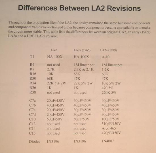
Different revisions of the LA2A used different resistance values.  22K for R34 was the original value, it was later changed to 10K.  It's ok to tinker with the circuit to make the end result what it needs to be.  I think it's more important to have the proper voltages at the tubes than have the exact resistance values for every resistor...if your voltages are off somewhere try using a higher or lower resistor value.

Check this out:

la2arevisions.jpg
 
airtech said:
Thanks for the help here. 

My voltages are 377volts after the diodes, 332 volts after the 4.7k,2w and 331volts after the 10k, not 22k, r34.

If you have essentially the same voltage after your 4.7K as after your 10K, then you're 10K is either not in circuit or there's a short where current is bypassing the 10K.  You should have a larger drop in volts across your 4.7K as well.  Are you using carbon or metal film?
 
The high voltage on power tube cathode means either the grid-resistor or the cathode resistor is open.

The high voltage everywhere means the tube is pulling low/no current. So the cathode resistor is open.

-OR- the heater is not hot. Look for the glow.

Powered-OFF, allowed to drain, measure resistance from power tube cathode (pin 2 here) to ground. I don't know the exact plan, but it will be many hundred to a couple thousand ohms.
 
The 4.7 and 10k 2 watter's are metal film.  Most of the rest are carbon comp's and a few others are metal film.
I'm still looking around for possible connection problems.  I'm still trying to figure out why there isn't a drop in voltage
at those points...including the other unit I built that works ok.  Could the tube be causing the problem?  A lot of the
other voltage readings I got from the other tube pins were pretty close.

The tubes are glowing.  I'll measure the tube cathode resistance to ground. 
 
I measured pin 2 of the 6aq5 and when I started it was at 9 or so meg.
It gradually went down to about 1.0meg or so.  I measured to ground.
Did I measure it correctly? 

Thanks again for the help.

Nate
 
I'm using 1/4 watt resistors by the way for all the other resistors other than the 2 2watter's.
Should I have used 1/2 watt?  I noticed this at the bottom of one of the schematic pages.
Jahnsen's book, I think, says 1/4 watt are fine.  I was told that the carbon comps sometimes
need to be ugraded to 1/2 watt in certain circumstances by a guitar amp repair shop. 

Here are the voltages I got:

la2_voltages_nate.jpg
 
clip an ohm meter from pin 2 of the 6bq5a socket pin and measure the resistance from there to ground.

it looks like either an open cathode resistor, wrong value resistor, or bad ground connection on the ground end of the cathode resistor.

resistors depend on the sound you want.

if you do use carbon comp, like way old scholl silver band 10 percenters, you want to use the biggest ones you can get for low noise.

2 watt is supreme, 1 watt is standard in botique guitar amps, 1/2 watt in stock fender which became noisy after many years, 1/4 watt for off shore stuff.
this hp volt meter that has a 1 millivolt full scale setting at the lowest end, has two plate resistors for every tube, and they are big 2 watt models.
or they used to be, i put in 2 watt metal film models all over the place.

screen resistors also.

adjust your pot with the screw driver, that always causes problems, the meter zero or stereo pot can both mess up your day.


> I measured pin 2 of the 6aq5 and when I started it was at 9 or so meg.

I have no idea why it went DOWN.... typically if you have the C but forgot the R it starts from zero and rises toward a Meg.

The plan you posted shows 1K. Ask yourself why you don't measure 1K from pin 2 to ground. Go step-by step from pin 2 to ground, noting resistance at each point.

This resistor or its connections is surely bad.

> trying to figure out why there isn't a drop in voltage

Half the total current is in V4. Or would be, if V4 were pulling current. When you get that 7mA going, the B+ will sag some. I don't figure it to hit the marked voltages, I think you will be at 290 where it says 275, but that's OK.

What is NOT OK (and not related to V4's problem): the voltage at NE-2 MUST be 50V-80V. There's wide variation possible, which is why there is a trim. But 135V is just not right. Either the NE-2 is not lit at all, or you have used a "120V Neon" (with internal resistor) when you must use a naked neon-bulb (no built-on resistor).

Neon-lamp regulation is appropriate for 1959, and until recently was a good choice for non-critical work in the 60V range. But neon bulbs have become hard to get, and the quality varies. We may finally turn to a Zener. Any 55V-60V Zener will be fine. If you get 0.6V, turn it around.

 
Well, I went through and made sure that the resistors were correct and came across all of the 470k resistors were actually 470ohm.
I bought them all from an electronics store in town and the little bag was mislabeled 470k.    I had gotten 5 470 ohms instead. 
So I went ahead and resoldered all new 1/2 watt resistors in (all of them) just to make sure all the values were correct.  And the unit works great.

And, all the voltage measurements are pretty close to the points on the schematic.

Only issue I'm having is the meter isn't showing the gain reduction.  I can hear it though.  When switched over to g/r, I can zero
the meter out, but the meter doesn't reduce(t), or whatever the hell, to the left like my other la2a does.  The meter actually kind of
very slightly goes to the right, only a little bit.  Any ideas on this one and where I should check?  Mysure  other meter is a cheasy Modutec and this unit is from an Ampex 440B.  Only difference is the Ampex VU has 2 extra terminals on the top with a resistor wired across.  Not sure if this is causing the problem.

Thanks again for your help.

Nate
 
Thanks for the help here and letting me talk things through with you all.  The vu wasn't working and I did another recheck of the wiring and noticed that the wires going to the R4 from the T1 post were incorrectly connected at the R4 pot.  Fixed it right away.  Calibrated the unit and it sounds great. 

I replaced all the resistors with carbon film and some metal film and was wondering if the original carbon comp that I had, even though it never worked and they were 1/4 watt instead of 1/2 and 1watt, make a difference with the sound.  I've also got some Sovtek 12AX7A's and was wondering if a JJ or different brand of tube would get me a little closer to the original sound.  I was wondering this since I've got the HA100x and the A24 transformers.  Since the unit is wired correctly, woulndn't mind redoing the resistors and maybe some of the capacitors all together to get a little closer to the original.  I've got orange drops and atoms.  Thanks for any tips. 

Nate
 
Not trying to be a douche-bag here...... Measure, measure and re-measure every resistor with a meter before soldering it in place. Don't depend on Mom and Pop to have labelled the bag or box correctly. Better to check them yourself with your meter before soldering into the circuit. This will save countless hours later. DW.
 
Tubemooley said:
Not trying to be a douche-bag here...... Measure, measure and re-measure every resistor with a meter before soldering it in place. Don't depend on Mom and Pop to have labelled the bag or box correctly. Better to check them yourself with your meter before soldering into the circuit. This will save countless hours later. DW.

That's good advice and I do that with every build these days, it's VERY easy to mis-read a 47k/470k/470ohm !!

Nice work and glad that you got it working properly :)

Marty.
 
Yeah, I spent a lot more time trying to fix it than building it.  I originally had it all breadboarded and then switched to point to point so I could see what was going on from above.  Replacing all the resistors with new ones and checking them first was the way to go. 

On another note, has anyone used the Multicomp Carbon Comp Resistors from Newark?  I was curious how they compare to the Ohmite Little Demon's.  They're about half the cost that's why I was wondering.  Thanks.

Another thing about the tubes:  I've got Sovtek tubes in this La2a. Is there a better or more accurate replacing?  Should I change over to a 12ay7 or 12at7?  Or a different brand all together.  Thanks.

Nate
 
my thinking is that you use resistor retro mojo for sound generating equipment.
and you use the clean resistors ie; metal film  for sound reproducing equipment.

so git and bass amps, carbon
mic pre, carbon/metal ( a mic pre is half and half mojo up front, metal to the rear)
mixing board: metal all the way
eq? metal
compressor? metal
microphone?  hmmm the jury is still out.

since the LA2a is a compressor, and therefor a sound reproducing unit, you do not want to add any character to the sound other that cool opto  compression.
so metal resistors, but...

the biggest sound improvement sometimes noted by the many builders has been the replacement of the output cap with a non lytic.

as far as original sound is concerned, you already have the transformers with the 20 k rolloff, (ask sll keef for the scope shots) so you have the retro sound with clean resistors.

if you want more silk, add a 12ay7 or 6072? to the V1 slot.

i have a version with 6sl7 and 6sn7 that sounds better than any carnation off this bench, so you can still make improvements.
 
Back
Top