LA3A 500 BUILD

GroupDIY Audio Forum

Help Support GroupDIY Audio Forum:

This site may earn a commission from merchant affiliate links, including eBay, Amazon, and others.
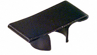
Do you guys know of a source for TO-18 heatsinks (or whatever the 4 can transistors are)?

All the ones available locally to me won't fit given the proximity of the surrounding components.
 
I was going to use these and see if they kept things cool enough. They physically fit. (with the boards mounted low with millmax pins - I ended up putting components on the underside of the board to get the sub boards low)
Mouser 532-578305B00


Attachments

  • HeatSink.jpg
    HeatSink.jpg
    2.9 KB
Those are what I use on my version and will work fine (provided they'll fit in your 500 space).

I originally used the circular "sun" shaped type but I found them a complete nightmare trying to get on.
 
dmp said:
I was going to use these and see if they kept things cool enough. They physically fit. (with the boards mounted low with millmax pins - I ended up putting components on the underside of the board to get the sub boards low)
Mouser 532-578305B00

I got that same heatsink and discovered (actually Winetree discovered) that with the taller millmax pins I mention earlier (see picture above) (2520 style) - those heat sinks are just slightly too tall to fit, due to the added 5/32s of an inch of the taller sockets.  Boo. I could probably shave down the heatsink a tad to make it fit.

So if using the taller pins, the only thing I've found that might work without modification are CTS 7175BA.

Untitled-1.png


Unfortunately, instead of 53¢ each, they're $2.35 each. I have them on order. I'll let you know if they work (*for anyone who cares / using taller pins.) And I'll ship them along with the correct trimmers.
 
Did you see that the thermal resistance of those heatsinks is higher - 58 C/w vs 38 C/W? I'm not sure how hot they will get, but if you have problems, I ended up being really happy with the millmax sockets I used. With the components moved over to the backside the boards fit in really nicely.
 
dmp said:
Did you see that the thermal resistance of those heatsinks is higher - 58 C/w vs 38 C/W? I'm not sure how hot they will get, but if you have problems, I ended up being really happy with the millmax sockets I used. With the components moved over to the backside the boards fit in really nicely.

Good to know! I bought a bunch of both types so I could do either. Seems like I may have wasted money on parts that aren't substantially better.  Very few heatsinks will fit with such tight component placement. Makes sense to use the one that's cheaper and better in terms of heat dissipation.

By the way Pete, I've been looking over your PCB. Genius work cramming an LA3A into a single 500 space. I would've thought it impossible.  *thumbs*
 
Sammas said:
Hey Kato, I've just finished butchering a kenetic t4b. I'll post some photos this evening (about 12 hours time here...). Hopefully I'll be powering it up as well, so I'll snap some pics. The El is a bright yellow in its off state. I'm assuming that because the EL and the photo cells were face to face in the original tb4, it is probably best to achieve the same thing on Peter's boards?

Was there a resistor in series with the light panel?
Many of the panels I'm finding online start giving off light with only 40v applied. I remember Kenetec mentioning on his site that the LSI branded ones start at low as 20v and that he used a resistor to raise that up a bit.

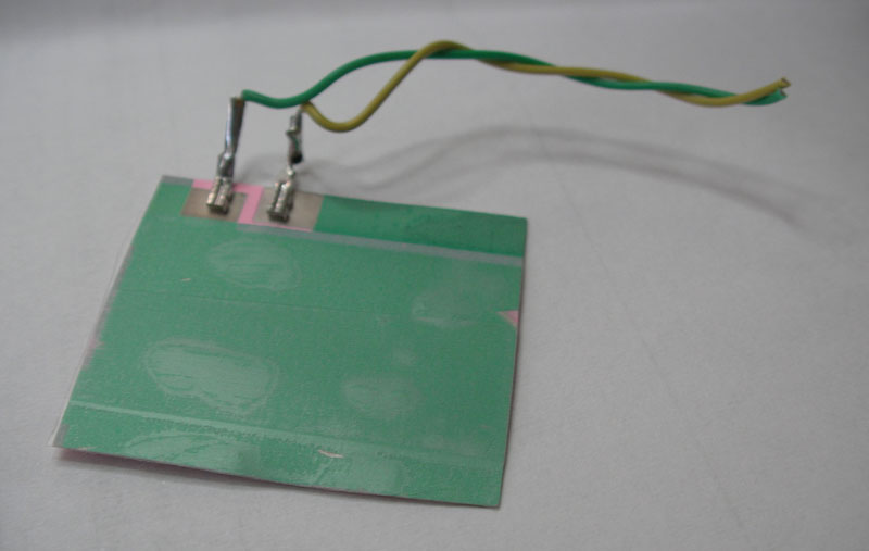
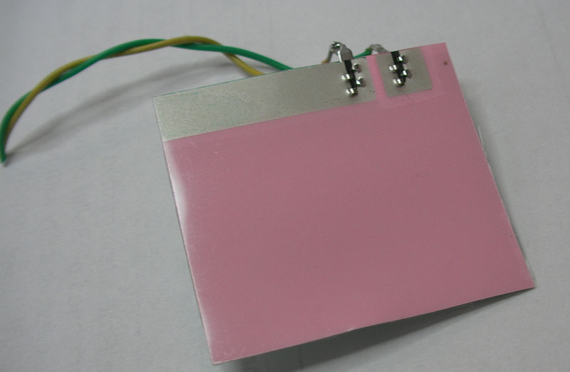
The panel inside my T-for-two is pink:

panel02.jpg


backside. you can see where I nicked the panel in two spots with x-acto knife. covered with scotch tape to keep the elements out

panel01.jpg
 
I back mounted 3 caps under the boards, and shortened the millmax pins,
lowering the boards to the top of the sockets. Gave a little more room for
the heatsinks but they still required some shaving.
 
kato said:
Sammas said:
Hey Kato, I've just finished butchering a kenetic t4b. I'll post some photos this evening (about 12 hours time here...). Hopefully I'll be powering it up as well, so I'll snap some pics. The El is a bright yellow in its off state. I'm assuming that because the EL and the photo cells were face to face in the original tb4, it is probably best to achieve the same thing on Peter's boards?

Was there a resistor in series with the light panel?
Many of the panels I'm finding online start giving off light with only 40v applied. I remember Kenetec mentioning on his site that the LSI branded ones start at low as 20v and that he used a resistor to raise that up a bit.


Hey mate,

Nope. No resistor in series with the panel. Just the standard .0047uf cap in there.

Here is my progress. Still yet to test (hence the reason I haven't glued the EL panel down yet).


Attachments

  • DSC00949.JPG
    DSC00949.JPG
    230.4 KB
Pete, you are the man. One of mine is tested, racked and burning in as we speak... I can hear a bass line bouncing through it and it sounds fantastic! Thanks again!
 
So finally I have some time to start getting this thing together.  Aside from the EL panel, the only thing I seem to be having a hard time finding is a source for the germanium diodes here in the states.  Seems like everyone who sells them is in the UK.  Anyone got a good spot?

  Brian
 
An update on the CTS heatsinks I linked to earlier. They arrived. They blow. Not recommended.
(Flimsy and bendable like a paperclip. Not worth the $$.)
 
hey guys, just a question about calibration and some anomalies in my LA3A.

When I turn the gain reduction past a certain point, the gain reduction meter suddenly jumps to -3dB when no input signal is present.

Is this normal? If it were just the noise floor of the unit causing compression I would have assumed it would be a gradual indication on the meter. Not a sudden jump like it is.

Also, which trimmer is the high frequency emphasis control? I'm thinking this might have a little to do with it as it is still set to the stock 50%.
 
Back
Top