LA3A 500 BUILD

GroupDIY Audio Forum

Help Support GroupDIY Audio Forum:

This site may earn a commission from merchant affiliate links, including eBay, Amazon, and others.
Pm'd!
Much thanks...
kato said:
Ianbryn11 said:
any news on a complete parts kit available? Just ordered the Hairball trafo kit...

I have enough overstock to assemble 4 or 5 kits. PM if you're interested.

$40 shipped (international additional) for all components, including relay, mill-max pins, etc. All quality parts. The electrolytics are low-impedence, high temperature, ceramics are C0G, etc. Same as I ordered for my own builds. Parts will be individually labeled with component designations for the LazPro pcb.

edit: you'll still need the T4b parts, transformers, and knobs.
edit for slight downward price adjust.
 
Sammas said:
Is it a Universal Audio T4B?

I'd be more concerned about the gunk holding the LDR's in place. Can you get them out without damaging them? 

It's just hot glue - came off pretty easily - although I nicked through the outer layer of the EL panel, stupidly using an x-acto knife. Hope it still works.

Also, it's not a Urei. I got it from Stayne many moons ago; it's practically vintage in it's own right.

If you have a UA branded T4B, it probably looks like the pics at Kev's site, I would guess. no gunk here: http://www.diyfactory.com/projects/diyla2/T4B1&2.jpg

 
20 X SOCKETS FOR 1MM PINS        575-029200      0292-0-15-01-06-27-10-0
20 X 1MM PINS      575-311720      3117-2-00-21-00-00-08-0
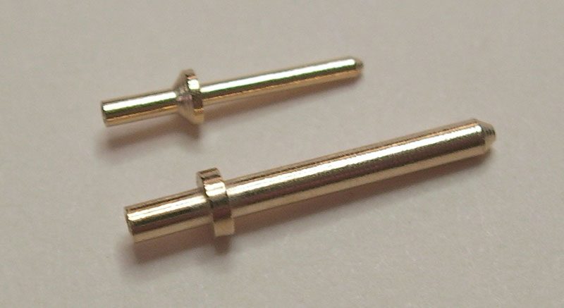
I got these parts in... the sockets work fine. I don't think the pins are worth the money - a little short and don't fit the holes well. It would be better to use the cut ends of diodes or some such. The pins need to be long since there are components under the boards.
 
unless the components are meant to be mounted on the underside of the board?? Like Gd1-4, decoupling caps, etc...
 
Okay, t4b received from kenetek, and put all parts apart :) now it's mounted on the LA3A  ::)

Just to get the last open things solved:

- If i have standard LED's how to i correctly solder them on the 3 pads ?
- Any trim instructions for RV31 and RV23 ?
- News on R13 ?

 
janvanvolt said:
Okay, t4b received from kenetek, and put all parts apart :) now it's mounted on the LA3A  ::)

Just to get the last open things solved:

- If i have standard LED's how to i correctly solder them on the 3 pads ?
- Any trim instructions for RV31 and RV23 ?
- News on R13 ?

For each LED, if you solder them on the two pads closest to the meter they will turn on when the button is depressed. If you solder them on the outside two pads (furthest from the meter for each respective LED), the will turn off when the button is depressed. Cathode is always the center-pad of the three solder pads.


Yeah, R13? Is it just 68k like the original?


Also, it is worth mentioning. I've received my transformers from hairball. The output transformer is ever so slightly too big for the cutout... best have the file handy (preferably before you start stuffing parts!). No biggy though.

 
R13.... as said before... I think I ended up with something like 10k. This was a balance between accuracy and adjustability.
You could try a temporary 50k pot there and fiddle with rv23 and the temp pot to get the best compromise, then stick in the appropriate value.
RV31 was wound fully one way or the other.... you'll see when you try it.
I don't have my prototype in front of me and not enough parts to build another, so maybe someone could report back.

peter
 
dmp said:
20 X SOCKETS FOR 1MM PINS        575-029200      0292-0-15-01-06-27-10-0
20 X 1MM PINS      575-311720      3117-2-00-21-00-00-08-0

DMP, For what it's worth, the "standard" (?) API style sockets fit the board better and seem a bit heftier. I bought some of each type to compare. Either could work fine but my gut says the 2520 style are worth the extra dinero.  - I'm talking specifically about the mill-max "0334" prefix receptacles - mouser: 575-034420 and pins 575-310320; not the "0322" prefix receptacles Jeff sells at ClassicAPI - which have an 85 mil base and look a hair too big to fit. So I guess it's not really a "standard." (I just don't want to lead anybody to parts that don't fit.) The ones I linked do fit. (As do the ones DMP mentions.)

Here's the difference in size between the two. Either of these will work:

pins.jpg


Anyway, I'm more interested in talking about that confounded T4B. Read CJ's photo cell measurements using a green LED as the light source. I measured a couple Silonex NSL-5910's this morning. Resistance decreases as the light source moves ever so slightly -  so you must keep cells equidistant from light while measuring. My numbers were way lower than CJs  because I'm using a bright magnifying light. Static resistance measured 40Ω on one, 29Ω on the other. Not a match. But probably matchable if I bought a dozen. Anyone with "slow" and "fast" version of the Drip want to measure the difference in cells? The NSL-5910 seem to be the standard cell in Drip and UA reissue T4bs. (And also the UREI tent sale ones from 2006.) Bill says "these cells have a little faster recovery time than optimal but I think they will make excellent sounding T4 units."

So what's the big secret? The panel? Anyone please describe the color with voltage applied when you get yours hooked up. I'm all ears.  I'm finding for sale panels of  "salmon color" variety in off state, and white or green when illuminated. Originals gave off white light I hear. (true?) But LSI panels in reissue are reportedly green. I may be misinformed. (I know  color will change with frequency change from resizing the panel.)

I'm interested in hearing your experiences. Panel size, light color, etc. Measure some cells for fun. Let's bust up this shroud of mystery.

Kato

PS - just for kicks I e-mail guy @ Clairex.com, makers of the photocells of yore. Their web site says 64 in stock. Gentleman replies thusly:  
We show some in Obsolete stock, but I'll have to get a hand-count to know exactly how many we have left.  The current price is $25 each with a factory minimum of $250.00; when these are gone, there won't be any left in the world.
So if you're interested in paying out the wazoo for notoriously inconsistent cells, you can!
 
Hey guys. Consider me daft... but how is the meter connected? Obviously +ve and -ve are marked on the back of the meter (big tabs), but what to PG & MP correspond to?


Hey Kato, I've just finished butchering a kenetic t4b. I'll post some photos this evening (about 12 hours time here...). Hopefully I'll be powering it up as well, so I'll snap some pics. The El is a bright yellow in its off state. I'm assuming that because the EL and the photo cells were face to face in the original tb4, it is probably best to achieve the same thing on Peter's boards?
 
PG = Power ground... to one side of the bulb.
MP = Meter power... to the other side.
Have the ldrs touching the el panel.
 
Winetree said:
I find it physically impossible to mount RV23 and RV31 because the front mount pots are in the way.
Is this correct.


They mount on the bottom of the PCB. If you dry mount the pcb onto the metal L-bracket, the screws on those two pots should be accessible through two little holes in the front panel.
 
Are you sure you have the right kind of trimmers? They need to be the horizontal variety.

Mine fit perfectly. Give me a few hours and I'll post a photo.
 
Sammas said:
Are you sure you have the right kind of trimmers? They need to be the horizontal variety.

My fault. I didn't realize those went underside and chose regular upright trimmers.

I'll get the right ones shipped out to the fellows that got parts from me. Sorry 'bout that.
 
Back
Top