LM334 questions, and it's role in this schematic.

GroupDIY Audio Forum

Help Support GroupDIY Audio Forum:

This site may earn a commission from merchant affiliate links, including eBay, Amazon, and others.
You would need two rms detectors conneced to a single threshold/volume/compression circuit.

Correct.

Again, correct.

What pin 5 and 15? Doesn't make sense to me...

That's called "analog OR"; that means the highest bidder takes the stake.

Yes, don't worry anout that (no pun intended).

That would be pin 4 on the 4315

Actuually yes.

Figure 6 of what document?
Wow! Things are coming up millhouse over here!
Thank you for your time, I appreciate it as always!!

- The pin 5 and 15 thing...ya, doesn't make sense to me either. Glad I'm not missing anything.

- I like the Analog OR thing! This seems like one of those 'tip of the iceberg' keywords that I'm going to research about later and be overwhelmed haha.

- Apologies, Figure 6 is the second document that I attached, however I cropped out the part where it actually says 'Figure 6.'

So, in summary, when connecting two of these 4315 One Knob circuits together, one only needs to connect

- The 'CT' pins (pin 4) together - on the IC side of the capacitor, of course.

- The 'RMS Out' pins (pin 5) together - which feed into one of those Threshold/Vol/Compression circuits (which in the case of the 'One Knob' circuit, is just the 'squeezer' circuit, for lack of better term). - But wont this do that doubling thing that we're trying to avoid? Or is that somehow cancelled out through pin 4?

Thanks again for the help! Now i'm getting really pumped about this haha.
 
Amazing. Thanks so much. I can't wait to build this thing and try it out! This one really excites me for some reason.
My wife thinks I've lost my mind.
I have.

Leaving things floating freaks me out. I feel like it just needs to go somewhere ha. But I trust you. And experience will eventually tell me when this is ok and when it's not.

When it's a single channel/mono compressor as in the original schematic, the Control Voltage output of the 'squeezer' circuit connects to the 'EC-' (pin12) of the VCA, which makes obvious sense.

In the case of a dual channel/stereo set up, now that there are now two thirsty VCA's looking for a control voltage, is it safe to just connect them together? Figuring that the same control voltage will simultaneously control both VCA's?

This too, seems like a no no to me haha
 
Amazing. Thanks so much. I can't wait to build this thing and try it out! This one really excites me for some reason.
In the case of a dual channel/stereo set up, now that there are now two thirsty VCA's looking for a control voltage, is it safe to just connect them together? Figuring that the same control voltage will simultaneously control both VCA's?
Yes.
 
Hi everyone, I hope you're all doing well.

I included a snippet of a schematic that came from here: THATCorp 4315 One Knob Squeezer PDF Link

It's a compressor circuit, and the snippet I provided is where the control voltage gets manipulated.

In my (tiny) brain, the LM334 is basically just an amazing resistor right? It 'sources current' and does it with incredible accuracy so...its an incredible resistor lol right? Why do I feel like I'm gonna get eaten alive for this sentence..

Anyway, in this circuit, very near to the 334 there is a "+VP" and "-VP" as well as an inverting op amp (U5A)...

- Is this small portion of the circuit actually creating a dual supply for the "more" potentiometer VR1? The '+VP' is also used for VR2, but nowhere else. I guess I'm a little confused what VP stands for lol.

- If I'm right (for the first time), and the whole point of this little 334 and surrounding circuitry is to create a dual supply for the purpose of the 'more' control, why not just use a charge pump at the power supply and run everything off of it? It would avoid having to DC bias anything, eliminate the voltage divider and buffer at the power supply...

- Is it because charge pumps (1044, for example) don't supply enough current? Or are unreliable?
The LM2662 could put out up to 200mA, but is 5.5V Max. Still, a 10V span for a small audio signal is quite sufficient...

Perhaps the THAT4315 wouldn't enjoy a dual supply, but for a similar price, the 4305 can. Hmm...


Thanks in advanced! Also, apologies in advanced for any toes I might have somehow stepped on without realizing lol.
When - ALL - of the dust settles on your idea of a "2-Channel/Stereo" One-Knob Compressor, could you please let me know that and either provide me a copy of the completed and finished schematic or a link to it? Since I do not know what your "end game" is with the circuit or if you have any plans to design a PCB for it, I am all set to electronically capture the finished schematic and get things ready for you of a PCB design. Enclosure too, if you need one. It could be anything from a small handheld enclosure to a 1U rack-chassis. Or, even a "Stomp-Box", if that's what you're looking for!!! Or, are you thinking of just building up a breadboard and mounting that into a small BUD box or Hammond enclosure?

Keep me posted, OK???

THANKS!!!

/
Haha, I feel like you're trying to sell me something so I'm immediately skeptical.
But I'm generally a skeptic anyway.

Yes, I'll definitely post the schematic and open it up to scrutiny - once I build it and prove it all myself first.

The lion's share of the schematic is not my original design, I'm mostly glueing a lot of other designs and ideas and lessons together, so it seems only fair to share it in case anyone else wants to build the same thing.

As for the pcb and enclosure design...I appreciate the offer!
But this is actually one of my favourite parts! 3D modelling the enclosure is a treat for me because I went to school for Mechanical Engineering. The PCB design is somewhat new to me, but I enjoy the challenge. And making them fit perfectly together is the stuff of my dreams.

Cheers! -Will keep you all posted
 
In this circuit, the LM334 (by virtue of R23) is generates a constant current of 120 µA. As this current flows in R20, it creates a voltage drop of +1.2 V, which is buffered by U3B to become +VP. Because U5A is a unity gain inverter (R20 = R19) the output of U5A sits at -1.2 V. So the circuit generates a stable, symmetrical ±1.2 V supply. This supply, is used along with the temperature-tracking +0.6 V reference generated by U3D, R24, and D3, to process the output of RMS to DC converter U2B. It is all some elegant circuit design indeed!
Because I'm too impatient to wait for the LM334 to arrive, and because my intended circuit will not run on battery, is it then reasonable to use a simple voltage divider to generate the symmetrical voltages?

Considering that they are +/-1.2V, centred around the DC Bias point of 4.5V, that would mean in reference to earth ground, the voltages are 4.5+1.2= +5.7V, and 4.5-1.2=+3.3V. Which makes me think I can press a few resistors into service and achieve similar results...

Is this correct? It's not quite as elegant or thoughtful haha, more like peeling an egg with a hammer. But if it works, it works!
 
Haha, I feel like you're trying to sell me something so I'm immediately skeptical.
But I'm generally a skeptic anyway.

Yes, I'll definitely post the schematic and open it up to scrutiny - once I build it and prove it all myself first.

The lion's share of the schematic is not my original design, I'm mostly glueing a lot of other designs and ideas and lessons together, so it seems only fair to share it in case anyone else wants to build the same thing.

As for the pcb and enclosure design...I appreciate the offer!
But this is actually one of my favourite parts! 3D modelling the enclosure is a treat for me because I went to school for Mechanical Engineering. The PCB design is somewhat new to me, but I enjoy the challenge. And making them fit perfectly together is the stuff of my dreams.

Cheers! -Will keep you all posted
NO!!! I am most certainly - NOT - trying to sell you anything!!! I am merely offering you some assistance since I just so happen to have a few decades of actual hands-on experience designing both mechanical chassis and all manner of PCBs.....together. I just thought that you might appreciate some help and insight on the physical design of your project idea. However, should you wish to go it entirely on your own, then by all means.....go for it and I wish you well.

So.....what 3D Mechanical CAD Design program are you using? I have the SolidWorks Premium 2021 package. I am including a link that shows several examples of the rack-mount chassis I have designed for various companies. Do you also design chassis like these?

Specific Rack-Mount Equipment & Rack-Systems Designs

[And, making them fit perfectly together is the stuff of my dreams] -- Yeah.....I know!!! You should have tried to design mechanical chassis and enclosures and all of their PCBs and then get everything to "fit together perfectly" in the days before CAD software!!! That was an entirely different beast back then and you had to stand at large drafting tables to do the work.

Since "making them fit perfectly together" is the stuff of your dreams.....then you - might - be interested in what I have recently done to resolve those issues. First, I purchased the SolidWorks Premium 2021 3D Mechanical CAD-design software, 2) Then, I purchased the CADENCE/OrCAD "PCB Editor" Release 17.4 PCB Design software, and 3) I then purchased a special program called "CADSync" that allows both my SolidWorks and CADENCE software to "bi-directionally communicate" with one another!!! What this means is.....I am now able to import a 3D CAD-model of a mechanical chassis into my PCB design software program and check for "fit/form/function/interference" between the mechanical chassis design and its associated PCBs or "vice'-versa".

So, I have been dreaming of this very same thing as you are now since 1979 and it has finally become an actual reality for me since I purchased these 3 CAD programs!!! And, this is why I offered to help you out. Your project isn't really all that complex or difficult, so maybe I could offer you some help along the way and I just dig designing stuff to build. But, > ONLY < if you want some help.

I am - NOT - a "Circuit Designer" and I couldn't design a circuit even with a gun pointed at my head!!! But.....give me a completed and working schematic and I will design you a fully-functional "first-article-build" prototype. Which, by the way, is what I do for a living. Check out Pages 7 to 11 in the link above and you will see a prime example of what I designed by working from a set of schematics. Is - THIS - what you want to learn how to do??? If so, I can help you out.....if you want. But, if you want to learn all about this entirely on your own, just say so and I will disappear, OK??? I'M NOT SELLING ANYTHING!!!

/
 
Haha, ok fair enough! I believe you. I do appreciate the offer.

I used to use Siemens Unigraphix on a massive old Linux system to do 3D modelling. But that was many many years ago before I actually quit the field of Mech Eng. in favour of touring with rock bands - my side hustle became my full time gig!

I did that right up until a few years ago when I quit touring with bands and started travelling the world for myself and as a video producer haha. So my 3D modelling is...quite rusty to say the least!!

If only Adobe made 3D software for engineers :(

Now, I'm using Fusion360/Eagle, which actually has the same 3D modelling and PCB link that you mentioned!
It's finicky, but it's great so far. I spend much less time with a vernier calliper these days. And usually the two parts mate almost perfectly the first time.

The trouble is finding manufacturers that will do the machining and the painting in the same shop...at a price that wont ruin me lol. Loads of Chinese manufacturers...but, I've seen a couple of those places in real life. It's pretty ugly. Hard to get past.

If I was back home in Canada where all my tools are, I could probably do a lot of the machining myself. But...covid etc etc.

I do appreciate the help!

If I run into a snag somewhere along this journey I'll be sure to post about it. I'm really enjoying the crowd sourced knowledge!

I'm always happy to chew the fat...so to speak.

Cheers pal
 
Because I'm too impatient to wait for the LM334 to arrive, and because my intended circuit will not run on battery, is it then reasonable to use a simple voltage divider to generate the symmetrical voltages?

Considering that they are +/-1.2V, centred around the DC Bias point of 4.5V, that would mean in reference to earth ground, the voltages are 4.5+1.2= +5.7V, and 4.5-1.2=+3.3V. Which makes me think I can press a few resistors into service and achieve similar results...

Is this correct? It's not quite as elegant or thoughtful haha, more like peeling an egg with a hammer. But if it works, it works!
For a temporary fix; you may want to tris this.
 

Attachments

  • Vp.jpg
    Vp.jpg
    69.8 KB
For a temporary fix; you may want to tris this.
Awesome! I will definitely try this!
Thanks for taking the time to draw that, I really appreciate it!
I was thinking of something totally different, so i'm glad I saw this in time ha! I'm breadboarding as we speak.

So to explain whats happening here:
- U3B is still just buffering, easy enough.
- U5A is going to flip whatever it sees onto the other side of 4.5V
- The capacitor is for stability (?)
- The 10k and 4148 Diodes create a voltage divider, the diodes are used because they will always 'divide' that same amount of voltage, regardless of variance in supply...right?
- The 2 100k resistors I can't explain yet. Not confidently. In one instance, they work together to keep the gain at unity. But I'm guessing the one pre-opamp resistor also creates a separation between the two op amps?

Thanks a lot for your time. I'm blown away at how helpful people are on this forum!
It's certainly in stark contrast to the rest of the entire internet!

Alex
 
- U3B is still just buffering, easy enough.
- U5A is going to flip whatever it sees onto the other side of 4.5V
- The capacitor is for stability (?)
All correct.
- The 10k and 4148 Diodes create a voltage divider, the diodes are used because they will always 'divide' that same amount of voltage, regardless of variance in supply...right?
Right, except that the "regardless" part is not so true.
- The 2 100k resistors I can't explain yet. Not confidently. In one instance, they work together to keep the gain at unity. But I'm guessing the one pre-opamp resistor also creates a separation between the two op amps?
It's an inverter. It takes the voltage on one node and flips it the other side of a reference voltage its non-inverting input sits on.
 
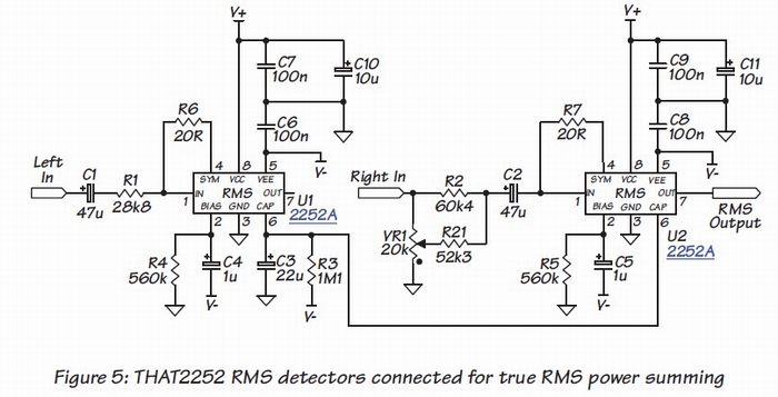
When the outputs of the RMS detectors are connected together (at the timing capacitor) to stereo couple two channels the result is a "true power sum."
Not sure that's been mentioned in this thread...

Also, another element with the LM334, besides temperature compensation, is that the regulated current source used to generate Vref provides regulated outputs which do not droop as the battery-powered supply drops. We owe Gary Hebert for this clever use of the LM334.
 
Last edited:
When the outputs of the RMS detectors are connected together (at the timing capacitor) to stereo couple two channels the result is a "true power sum."*
This is debatable. The port that drives the timing cap is the emitter of a transistor. Connecting two or more results in a analog "or", so the actual voltage is that resulting from the highest signal.
True "power summing" woud require extracting the signal power of each channel and summing them. It would require a rather complex circuit, and moreover, would not be a useful function.

Mea culpa.
 
Last edited:
This is debatable. The port that drives the timing cap is the emitter of a transistor. Connecting two or more results in a analog "or", so the actual voltage is that resulting from the highest signal.

I disagree.

1) Although it is transistor emitters that are tied together they are diode-connected transistors.
2) You'll need to debate THAT who have used the term in their application notes. https://thatics.com/datashts/dn116.pdf

True_Power_Summing_2252.jpg


3) I know from having done it (have you?) that when two "RMS" detectors are connected together in this fashion that the output, in the log domain, increases by an amount equal to 3 dB, not 6 dB, nor the greater of the two, when equal level inputs are summed in this manner. It IS NOT the highest of the two.

I am the person who showed Roger Foote how to configure the Pico Compressor for True Power Summing on this very forum in 2007.

Pico_Compressor_Mad_Scientist.jpg


4) EDIT: See also THAT DN-118 https://www.thatcorp.com/datashts/dn118.pdf
 
Last edited:
We have been around this tree before... I am not a fan of calling it "true RMS" (a play on log domain math for marketing ) but agree the multed together log output nodes are not a simple "or" function.

JR

PS: Was this project (Roger's compressor) why you guys left? In case I haven't shared lately, my interest in your DC coupled phantom voltage mic preamp is why I joined this forum.
 
1) Although it is transistor emitters that are tied together they are diode-connected transistors.
It doesn't make a difference. The Shockley equation is valid for all sorts of PN junctions.
2) You'll need to debate THAT who have used the term in their application notes. https://thatics.com/datashts/dn116.pdf

True_Power_Summing_2252.jpg


3) I know from having done it (have you?) that when two "RMS" detectors are connected together in this fashion that the output, in the log domain, increases by an amount equal to 3 dB, not 6 dB, nor the greater of the two, when equal level inputs are summed in this manner. It IS NOT the highest of the two.
Of course it is not the highest of the two. I used the term "analog-OR" as a simplification.
And I stand corrected regarding the power summing.
 

Latest posts

Back
Top