


dagoose
Well-known member
I'm going to implement a lm3916 vu meter into my gssl and i have some questions about it.
What i want to do is make it switchable between input and output and so i'm looking for decent points to sniff the signal.
I was thinking of using the same points as the crush and blend installation by livingnote since they are unbalanced and are 'tapped' anyway.
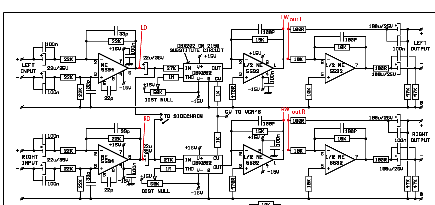
Is this a good idea or should i use other points maybe because it will degrade the signal to much in combination with the crush and blend?
I was also thinking of just using the + and ground side on the real input and output (so on the xlr plugs that is) but i think it might give some problems with impedance then.
I'm also thinking about the summing of left and right since it will be just a 'mono' vu meter.
Will resistors of something like 47k do the job or is there another better way to do it? I know Livingnote was working on a different version but I want to keep it as simple as possible.
About the lm3916, since it is based on consumer levels (?) i think the input needs some changes to give real VU scale values. Is there a standard thing to use for the input?
http://www.datasheetcatalog.org/datasheet/nationalsemiconductor/DS007971.PDF
What i want to do is make it switchable between input and output and so i'm looking for decent points to sniff the signal.
I was thinking of using the same points as the crush and blend installation by livingnote since they are unbalanced and are 'tapped' anyway.
Is this a good idea or should i use other points maybe because it will degrade the signal to much in combination with the crush and blend?
I was also thinking of just using the + and ground side on the real input and output (so on the xlr plugs that is) but i think it might give some problems with impedance then.
I'm also thinking about the summing of left and right since it will be just a 'mono' vu meter.
Will resistors of something like 47k do the job or is there another better way to do it? I know Livingnote was working on a different version but I want to keep it as simple as possible.
About the lm3916, since it is based on consumer levels (?) i think the input needs some changes to give real VU scale values. Is there a standard thing to use for the input?
http://www.datasheetcatalog.org/datasheet/nationalsemiconductor/DS007971.PDF
")


