> The frequency resolution is important for high-resonance situations
Yes.
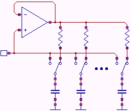
> any way to get a capacitor that switches "in" to be near the same potential
Connect them with low-value resistors. But that screws your frequency response. Unless these resistors ARE the response shapers.
A 2-pole low/band/high-pass filter is 2 R 2 C and 4 opamps. If you fix the C and switch the R you don't have big stored charge. The straight-ahead approach has neither end of the Rs grounded, though it may be so near ground it isn't really "floating" and an FET or 4051 may be a fine switch. There is a variant where DACs are used ad digitally controlled analog attenuators, which make a fixed integrator resistor act "variable" (or if current-output you don't need a fixed resistor). Many ways to swing cats; in this case I'm thinking you swing the Rs not the Cs.
For an ancient observation: the H-P 200AB sine oscillator uses a huge mechanical variable capacitor. When you sling the knob rapidly the stored-charge throws the system into a wobble. No switching (over 1:10 range) but that ~~1,000pFd going to 100pFd or back throws 900pFd of charge around the loop. You switch Rs for range-change; these kick but not near as much.
> I think it's worth playing around with. I've always learned the most from situations like this
Yes. Most good ideas are bad ideas beaten into something else. Wrestling with the bad idea gives you a clue where to beat, and where to take a different path.
If you needed it to Work Real Soon, I'd advise a dumb old analog VCF fed from a DAC. It works. It does have noise issues. We could use somethig else.
Yes.
> any way to get a capacitor that switches "in" to be near the same potential
Connect them with low-value resistors. But that screws your frequency response. Unless these resistors ARE the response shapers.
A 2-pole low/band/high-pass filter is 2 R 2 C and 4 opamps. If you fix the C and switch the R you don't have big stored charge. The straight-ahead approach has neither end of the Rs grounded, though it may be so near ground it isn't really "floating" and an FET or 4051 may be a fine switch. There is a variant where DACs are used ad digitally controlled analog attenuators, which make a fixed integrator resistor act "variable" (or if current-output you don't need a fixed resistor). Many ways to swing cats; in this case I'm thinking you swing the Rs not the Cs.
For an ancient observation: the H-P 200AB sine oscillator uses a huge mechanical variable capacitor. When you sling the knob rapidly the stored-charge throws the system into a wobble. No switching (over 1:10 range) but that ~~1,000pFd going to 100pFd or back throws 900pFd of charge around the loop. You switch Rs for range-change; these kick but not near as much.
> I think it's worth playing around with. I've always learned the most from situations like this
Yes. Most good ideas are bad ideas beaten into something else. Wrestling with the bad idea gives you a clue where to beat, and where to take a different path.
If you needed it to Work Real Soon, I'd advise a dumb old analog VCF fed from a DAC. It works. It does have noise issues. We could use somethig else.