Looking for speaker DC protection ideas..

GroupDIY Audio Forum

Help Support GroupDIY Audio Forum:

This site may earn a commission from merchant affiliate links, including eBay, Amazon, and others.

Viitalahde

Well-known member
Joined
Nov 7, 2005
Messages
727
Location
Kuhmoinen, Finland
As a part of my active 3-way speaker project, I'm searching for ideas in DC protection of the speaker drivers. This includes the basic ON/OFF thump muting and also amplifier malfunction DC detection.

http://sound.westhost.com/project33.htm

So far this is the best one I've found. It does have a few shortcomings though..

1) It does not latch. I think the amplifier should go into steady "error" state when DC is detected at amplifier outputs, and this should only be reseted with shutdown. In case something fluctuated at the outputs, the relays would be tripping back & forth, giving a low-frequency square wave @ +/-45v to tweeter.. Doesn't sound quite right to me.

2) It relies on voltages from amplifier rails. Not that a big of a deal, but just in rare case the rails start acting funny, I think it'd be good to have the protection circuit on a small, reliable power supply.

I've been thinking all day of better methods.

One idea for "The Brain" was to make a bistable multivibrator out of an OR gate by having a feedback to one of its inputs.

http://www.allaboutcircuits.com/vol_4/chpt_10/1.html

If this input was grounded with 10k resistor, I was hoping it'd give a steady "0" until "1" is seen at the other input (from the DC detection circuit). This could be a pretty steady latch, but the power-up was my concern. I want zero to begin with.

The other idea was to have a mechanical latch out of an additional relay that, when activated, shorts the driver transistors of the protection transistors and puts the whole relay bank in a sort of a feed-back that keeps the relays in safe position.

This circuit from DiyAudio.com does something like this (RL3 center down) http://img.photobucket.com/albums/v240/virtalahde/dc_protect_in_rush_fab.jpg
..But I don't get the detection circuit. How is it supposed to detect negative voltages?

Haelp!
 
DC protection is often offered in professional power amps to prevent expensive speaker damage when output devices fail (typically shorted to one rail or the other.

Amps with output relays typically sense for some threshold of LF and open the relay. Another approach that is somewhat cheaper is to shunt the power amp output to ground through a power device and take out the PS fuses or circuit breakers when DC is detected.

The shunt can be a little dicey in very high power amps, and relays have been known to arc over and weld closed so none of these are fail safe but will protect against most events which is all you can hope for.

There may be issues with discriminating between DC faults and valid LF content for extreme Fi. I guess one could configure the detector to ignore input signals and only respond to fault output voltages, but this wouldn't protect against a DC failure upstream (more common with dc servo than cap coupled designs).

Have fun..

JR
 
I hate the idea of relays in the signal path, other than in shunt. You will eventually get low level "dry" contact intermittencies, unless they are big honking Hg displacement relays (the power counterpart of mercury-wetted reeds).

If you apply feedback around the relay contacts it helps a bit.
 
I thought of shunting, but it seemed pretty brutal.

I'm using the Hypex Class D modules, and here's a reverse engineered schematic from their protection circuits (the first schematic of the page):

http://home.wanadoo.nl/dezaire/UcD180AD/UcD180AD.htm

I don't know.. It doesn't protect the speaker in any way since it just cuts off the rails (OK, it does but not directly), but it seems to me it at least latches. From the looks of the original circuit board, the relays are the basic ~5A devices.

The Hypex modules should have a pop-free start, but I thought of having the function in my protection circuits too since it's just a few parts.

The relays are definately another headache. So far I've found pretty much zero relays that would be capable of breaking a few amps at 45 volts, let alone 70 volts the amps of the bass drivers use. I did find a pretty nice relay that was guaranteed for high inrush current - over 100A for a short period of time. This would help with welding contacts, but I really don't know if I want to put my tweeters through them.

John, I'm having a lot of fun. :? :razz:
 
would i be totally lame by offering a cheap tv circuit breaker red plastic "your turkey is done" botton on the back of the speaker?
they seem to work, but after multiple trips, they get weak.

the other boundry condition would be a Cray Super 2 monitoring the signal with a plethora of dsp kernels, parallel processing both channels at the same time and computing the hyperbolic cosine, if you get me?

as the Rev G says,

"And all points in between..."

I will put this down on my AES shopping list, there are many speaker protection papers on file at the library.

cj
 
Another area I know little about. I recall hearing about use of magnets to prevent relay arcing from causing them to stick but this was second hand from a not tech type.

Series relays may not be ideal but have been widely used and should be OK if properly sized. I would be less apprehensive about dry contacts at speaker level currents. Feedback is sometimes applied around relays and contacts over rated to deliver numerically high damping factor specifications where milli ohms of series impedance matter. Some customers believe high DF is important and customers are always right even when they're wrong.

Turning off the power supply rails should work as another alternate protection scheme (not for dethumping) , but will ultimately depend on robustness of those switches. If the amp failure mode is PS related switches may be compromised too.

Shunt is not that bad. Properly designed amplifiers will tolerate shorts to ground until they thermal cycle off so primary design issue is that shunt device can handle the PS energy until fuse or breaker opens without failing as a short itself (it happens).

JR
 
Overheat Protection Circuits for Moving-Coil Loudspeakers
Voice-coil overheating is a main reason for loudspeaker damage and failure. It is shown that the voice-coil temperature depends linearly on the so called -moving power.- Knowing the basic thermal parameters of a moving-coil loudspeaker, its isothermal diagram can be determined in a Power-Time domain, defining the -Safe Operating Area- of the loudspeaker. It is clear that the protection circuit should maintain the input signal level within the safe Power-Time limit. The effectiveness of existing protection circuits have been estimated, and some new protection circuits for active and passive loudspeakers, are presented.
Preprint Number: 3036 Convention: 90 (January 1991)

Complete Thermal Protection of an Active Loudspeaker
The paper describes the implementation of thermal protection in an active loudspeaker. The protection system has been designed to protect the loudspeaker drive units from any signal that can cause thermal damage to the units. The protection has also been designed so that the loudspeaker can generate the maximum sound pressure level for the longest period of time and can be subjectively acceptable.:
Preprint Number: 5112 Convention: 108 (January 2000)
Author: Chapman, Peter John


Lamps for Speaker Protection
Incandescent lamps have been used for over fifty years as loudspeaker protection devices, but a large amount of misinformation about them exists. The author measures static and dynamic parameters of over thirty types of auto lamps, as well as tests some types for consistency between manufacturers and production. The results contradict a lot of the common wisdom about using lamps for protection and show serious linearity problems even at low operating levels.
Preprint Number: 5881 Convention: 115 (September 2003)
Author: Dorsey, Scott

An Electronic Loudspeaker Enhancement and Protection Device
An electronic speaker enhancement and protection device is described. Using precise electronic modeling of the behavior of a dedicated loudspeaker system, it allows safe operation at maximum temperature and excursion limits, and optimizes the frequency, time, and dynamic response of the loudspeaker. This is accomplished without any dynamic variation of bandwidth or crossover frequency. The specially-designed loudspeaker system is optimized to produce maximum output with high efficiency and low distortion, in a compact, arrayable enclosure.
Paper Number: 6-030 Conference: The AES 6th International Conference: Sound Reinforcement (April 1988)
Author: Miles, Michael T.

and it goes on and on and on,


just use really big drivers and you dont have to F with it all.
 
[quote author="CJ"]

just use really big drivers and you dont have to F with it all.[/quote]

...or a line array of good speakers. Mine are rated for about KW in sum while I need up to 20 W from them.

left_array.gif
 
The modeling approach will probably win out as more DSP get imbedded in powered speaker electronics so it has low incremental cost other than coding.

One technique that I have speculated about when you also have visibility into the current being drawn by a speaker (like with some commercial instal amplifiers), is to compare cold current draw vs. hot to literally measure the temperature rise of the VC wire from it's resistance increase.

The DSP modeling approach may be more useful in long run as you can also predict rate of temperature change and more intelligently manage your mitigation.

JR
 
This is all good information here, thank you.

I've given more thoughts to the shunt idea, and I'm beginning to like it. I could combine it with relays switching the voltage rails out, this would be safe for both amplifier and the speaker driver.

Now my consideration is the number of relays.

Six amplifier outputs equals six relays..
Six amplifiers, each with two voltage rails = 12 relays (6 if dual relays)..

Doesn't sound too sensible. :?

What if I just cut off the mains from the transformer primary, before the fuse? I'm going to have a soft start circuit anyway, so I'll be able to fit in a smaller quick-blow fuse that should trip pretty quickly when the amplifiers would be shunted to ground.

This would prevent any further damage if the fuse didn't blow for some odd reason. I don't want it to become a welding machine from hell. :razz:
 
If you have in your home theater a remote control and "sleep" mode it will be easy to cut it off "
before a fuse". You may use as well the same PS and relay used in remote receiver.
 
wavehead, i need a list of the 8 drivers in the wall, the two 12's in
the floor, and i bt there is a sub in there to boot.

jako, here is a weird idea, but it might work.

current sensors. we make them.
you snap one over the speaker line, and feed the output into your
relays.

true rms, even a delay on some models, i might have
one "floating" arounfd the shop somewhere, if ya get me?

http://www.nktechnologies.com/content/download/ASX_Series.pdf
 
[quote author="CJ"]wavehead, i need a list of the 8 drivers in the wall, the two 12's in
the floor, and i bt there is a sub in there to boot.

[/quote]

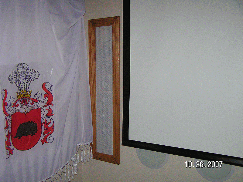
Infinity Reference 4.5 inches in walls (and couple of Infinity Reference 6.5 inches for effects in the middle and couple on a back wall). The rest of round grills under a screen are sound traps (10 of them). A flag with the family herb covers a memory foam mattress to minimize reflections from the left wall. A bigger mattress is mounted on a back wall, it is covered by phony curtains.
Woofers are Alpine 12 inches in concrete boxes (made with help of 12 gallon plastic enclosures), one per side, plus for below 30 Hz I have a concrete gramophone buried in sand under a floor.
You are welcome to bring a movie with your favorite sound track to test it in person. When we watched The Night in The Opera shaking sofas impressed my guests. ;)

However, I am going to remove Infinity tweeters and put 64 per column 1/2 inch tiny speakers to eliminate comb effect on highs that presents theoretically.

Here are more pictures: http://www.wavebourn.com/forum/viewtopic.php?f=7&t=934
 
Wow!
I bet the termites have a real problem sleeping at your place!

HCan you tune the concrete boxes for resonance,how?
Maybe a tunable port with an air chisel or masonary bit?
 
[quote author="CJ"]Wow!
I bet the termites have a real problem sleeping at your place!

HCan you tune the concrete boxes for resonance,how?
Maybe a tunable port with an air chisel or masonary bit?[/quote]

No need for ports when I have plenty of space and drivers with low enough Fs.
 
Just a quick note: a shunt wont work well with the Hypex modules as they are not short-circuit proof (they should, but at least one was not). Well, it will protect the speaker but kill the amplifier.

Samuel
 
Deducting from Diyaudio.com threads I would use a high quality cap in series of the tweeter and midrange. It seems though thath UcD needs a resistive path to ground in it's output, like a 100 ohms (-> 1 kohm) resistor connected directly to output before the cap and the tweeter.

http://www.diyaudio.com/forums/showthread.php?s=&threadid=100792&highlight=

Using a relay either to cut the signal to speaker or disconnect the power is always risky (the contact may be already welded). Maybe there are other kind of components that could be more reliable, maybe circuit breakers ( http://en.wikipedia.org/wiki/Circuit_breaker ) with some appropriate driver electronics could be used? Once you detect the DC you could just explode the PSU or short (shunt) the mains to activate your house circuit breaker, that would save your drivers (hopefully).

However, it's no wonder why many commercial speakers built using the most expensive speaker elements (like the JBL DD66000) usually have a passive crossover network (and quite a complex one, too: http://manuals.harman.com/JBL/HOM/Technical%20Sheet/Everest%20DD66000%20ts.pdf ).
 
I know it's not in the spirit of the thread but why not just throw caution to the wind and in the unlikely event of catastophic failure buy a new driver. It's seems like an awful lot of trouble for something that is for personal use.
 

Latest posts

Back
Top