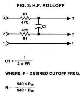
Low pass filter for balanced line level

GroupDIY Audio Forum

Help Support GroupDIY Audio Forum:

This site may earn a commission from merchant affiliate links, including eBay, Amazon, and others.

wkbdgeorge

Well-known member
Joined
Dec 19, 2008
Messages
92
Location
Belly of the beast
Hey everybody.  I am hoping someone can enlighten me on how to accomplish a low pass filter for a balanced line level signal.  Basically, I want to cut the highs down to around 100 or 200 hz off a balanced signal cable. 
   
Is this possible without unbalancing the signal?  I am looking for an easy-ish way.  I dont know how to make a differential amp to unbalance the signal and I dont think i have any spare transformers laying around. 

I was thinking of 2 ways:  Either i match the resister and capacitor as best as i can for both the high and low lines and hope that doesnt throw the cmrr off.  (would that even matter??)  ....... Or...... I tie low to ground and only do a rc network for the high signal.

I really appreciate any insights that somebody might have on this.  Thanks!
 
Thats great PRR!!  Thanks so much.  I have a couple questions for you if your willing.....

-I take it that because the two are tied together through the cap that its as if just one side is seeing a 1uf cap to ground?

-Also, would it be possible to use a dual gang pot instead of the  two 1k fixed resistors?  If not, no biggie, but it would be way easier to find the perfect frequency for the job.

I apologize for my lack of knowledge. 
 
I was searching about this recently as well. I was actually looking for the equations to solve a certain passive low-pass, or high-pass filter frequency/cap/resistor for a balanced line, but due to not knowing the exact terminology I could not find it.

[edit]

based on the PRR image I found this: http://www.muzique.com/schem/filter.htm

works ok with dividing the single resistor value to two for the floating balanced halves. But how do I take into account source/destination impedance if I want to use this for more calculations?
 
gadget-3.jpg


Various other handy gadgets described as well:

http://www.ethanwiner.com/gadgets.html

and more:

http://www.ethanwiner.com/micpolar.html

etc


Bye,

  Peter
 
The input impedance of the following stage will be in parallel with the 1Ks, the output impedance of the source will be in series with 1Ks.  Source impedance will shift pole down, input impedance will shift it up... Should be close enough for government work unless source impedance unusually high, or input impedance unusually low.

JR
 
> how do I take into account source/destination impedance

My solution is exact for zero source infinite impedance.

Most audio interfaces attempt to approximate this goal, kinda-sorta.

As John points out, source error leans one way and load error leans the other way. If the resistor is picked half-way between realistic impedances, you hardly know the difference. 2K is midway between <470r sources and 10K loads. 1K or 4K (total) will work too.

Anyway, this is a friggin' 6dB/octave filter! 30% component tolerances give just-audible shift of frequency. It is perhaps "expecting too much" to use a pot; a half turn is a very mild change.

wkbdgeorge did not specify any context except "balanced" and "low-pass 100-200Hz". Balanced 600 ohms matched? Balanced 47r source and 47K load? wkbdgeorge did not say if the highs had to be shaded or killed, how steep the filter should be. Instead of goals, the thought wandered off into bal/unbal befuddlement, implementation complications, and supply shortages.

So I threw a capacitor at him. It will work. Because the actual impedances are not known, I tossed a couple resistors to swamp the likely gear-impedance. Since the corner is very un-sharp, and the specified 100-200Hz is broad, no real precision is warranted.

A 6dB/octave slope at 200Hz is only 20dB down at 2KHz. Guitar-scream etc will be reduced but not silenced. A mono subwoofer with strong 1KHz peak will contaminate stereo soundfield. If the lame filtering is a problem, wkbdgeorge will have learned something: ponder the filter steepness. Slow slopes are easy, steep slopes are complicated and fussy, so this is a key design feature.

A 12dB/oct slope could be done, passively, with a couple 1H chokes, the cap, and maybe a resistor to control the bump. Chokes in audio are problematic. Amplifiers with R-C networks avoid those problems but introduce new ones.

So I threw a capacitor at him. It will work. If it don't work good enough, at least it leads to better understanding of the problem, more insight.
 
Your exactly right PRR, The end use of this idea is not a critical situation.  I ended up putting a dual deck 1meg pot in instead of fixed ones.  Im using a .47uf polyprop cap between the high and low.  Im going to used the pot to sweep to find the perfect frequency range and then document that resistance, then change to fixed resistors.  

Ive created the ugly monster to test in circuit and it works! ;D  Once I find the right resistor this will be a nice little cable.  Im basically trying to make a faux 3 way speaker setup.  I have 2 sets of powered monitors.  My main ones are dynaudio bm5a's.  They a good speakers but there is no bottom below 60 or 70 hz.  So im using a second set with these filters inline to make use of the larger woofer to more accurately reproduce the lows.  Of course there is going to be quite a bit of tweaking of the front to back placement of extra speaker and also the 1meg pots to find the sweet spot, but thats why we have ears right?

I didnt want to give that info at first because its interesting to see what the advice is for the info given.  Otherwise minds start to wander and wonder why the hell i would even waste my time with such a thing. haha.  

-George
 
PRR said:
A 6dB/octave slope at 200Hz is only 20dB down at 2KHz. Guitar-scream etc will be reduced but not silenced. A mono subwoofer with strong 1KHz peak will contaminate stereo soundfield. If the lame filtering is a problem, wkbdgeorge will have learned something: ponder the filter steepness. Slow slopes are easy, steep slopes are complicated and fussy, so this is a key design feature.

yes I also did not specify what I was looking for in detail. It was 1st order high-pass filters for balanced line. They will exist in a vari-mu compressor, just before audio enters sidechain input transformer so 600 ohms matched is ideal. 6dB/octave is preferable, as is simplicity, accuracy less so. I just want to transparently remove excess bass entering sidechain, if I never decide it's needed.
 

Latest posts

Back
Top