Math Geniuses - PM1000 EQ Schematic pic Need proofread help

GroupDIY Audio Forum

Help Support GroupDIY Audio Forum:

This site may earn a commission from merchant affiliate links, including eBay, Amazon, and others.
T

tubejay

Guest
I'm about to try to modify my EQ on my Yamaha PM1000, and I'd really appreciate it if someone could verify my math here before I order some caps. Many people have talked about doing this (myself included) and I don't know of anyone who's actually done it yet. So I'm about to dive in head first, because the EQ on this thing is really pretty silly as is. I'm basing this mainly off of this website:

http://www.krashjones.com/pm1000/#Thoughts_On_Reworking_The_EQ

I'm going to try to make the midrange be as follows:

From 1KHz to 700Hz by changing the caps from .15uf to .27uf film caps
From 2KHz to 1.6KHz by changing the caps from .068uf to .1uf film caps
From 4KHz to 3.2KHz by changing the caps from .033uf to .051uf film caps
From 10KHz to 12KHz by changin the caps from .047uf (C15) to .039uf film caps

Here's the original schematic from the PM 1000 EQ section:

PM1000EQSchematic.jpg

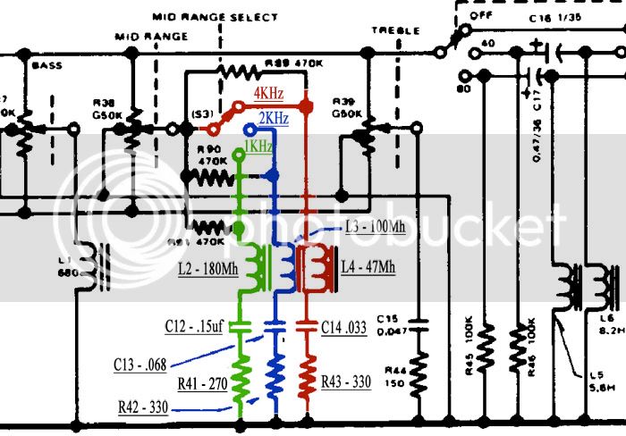
On the schematic the inductors should have all been labeled mH, not Mh.

Here's the full Yamaha PM1000 manual, which has the FULL schematic:

http://home.new.rr.com/lordjimbo/PM1000E_2.pdf

I tried figuring the EQ points out myself by using this website:

http://www.opamplabs.com/cfl.htm

However, I think that because of the resistor inline with the cap and inductor on each band, this isn't working. If anyone could instruct me how to figure this out myself, that would be most helpful. I'd like to put in a band around 350Hz and 7.2KHz on some of the channels as well.

So the big question, does this look about right???
 
Anyone daring enough to take a whack at this? Come on! I don't care if you're not 100% right, or sure, or whatever. Opinions welcome!!

I was also curious what C16 and C17 are there to do in the low cut filter. Do those set the frequency, or do they do something else. I was thinking of trying to make the 40Hz filter into a 150Hz filter instead.

Come on brave souls, I know you're out there!!

I'll give you a :guinness: and a :grin: !!
 
Since you are changing just the C of an LC circuit, you have to super-size the change, square of frequency difference.

You should also change the resistance values, but for these small changes it won't be much different, and these resistances are fairly arbitrary. They set the height/depth of the bump/dip at the extreme of rotation, so if you "want more-more", reduce the ~300Ω resistor to taste.

> From 1KHz to 700Hz by changing the caps from .15uf to .27uf film caps

I get 0.306uFd

> From 2KHz to 1.6KHz by changing the caps from .068uf to .1uf film caps

I get 0.106uFd

> From 4KHz to 3.2KHz by changing the caps from .033uf to .051uf film caps

I get 0.05156uFd

> From 10KHz to 12KHz by changin the caps from .047uf (C15) to .039uf film caps

This one just goes AS frequency (not an LC). I get 0.039167uFd

This type EQ has very low Q except at the extremes. I'm not sure these changes will be really audible except when you turn the pot to the end.
 
Thank you PRR!!!!!

How did you do the calculations? If it wouldn't impose too much, could you show me the calculation you did for the 700Hz band or any band for that matter. I've found several people that have cap values to put in there, but nobody seems to know how to do the calculation themself.

I know this is probably beginner stuff, so I apologize if this is a stupid question.

Thanks,

Jay
 
Center-frequency of an LC network is proportional to 1/√(L*C)

The ideal way to change frequency is to change both L and C by the inverse of the frequency ratio. If 1KHz is 180mH and 0.15uFd, and you want 700Hz, then you want frequency to change by 0.7, you want L and C to be (1/0.7)=1.43 times higher. 0.15uFd*1.43= 0.215uFd, 180mH*1.43= 257mH.

BUT: chokes in arbitrary values are hard to get. Caps you can get any size.

If you want to change frequency by JUST changing the cap, you have to change it a lot to get around the fact that you did not change the choke.

In 1/√(L*C), you have to change the cap 4 times to change frequency 2 times. So from 180mH 0.15uFd 1KHz to 700Hz means the cap has to be bigger by (1/0.7)^2= 2.04, the square of the (inverse) frequency ratio.

As I was walking-off my last post, I realized a specific flaw in this logic applied to this circuit. This is a very low-Q circuit. The L and C don't really resonate. So when you change just the C, you only change the low-side of the curve, not the high-side:
700Hz-C.gif


I don't think the curves are ever this sharp except at FULL cut-boost. As soon as you come off the end-stop, that 25K pot-resistance adds hundreds of ohms and cuts the Q.

The top-shelf is not a semi-resonant circuit, so the nominal frequency is just (inverse) proportion to the cap.

The 40/80Hz filters are set by the C16 C17 caps but also the chokes, and the bump/dip at the corner is set by both source and load impedance. If you try to change 80Hz to 160Hz by quadrupling C17, you will get about a 6dB bump around 160Hz, probably not what you want. With all the other crap happening here, I think the most sane way to shift these filters is to change both L and C by the amount of frequency shift (inverted). C17=0.24uFd, L5=2.8H, something like that (0.22uFd and 3H might be fine).
 
So I finally got the parts to do this. The film caps are a LOT bigger than whatever was in there before. It looks messy, but I think it should be fine. I had to extend the legs on two of the bigger caps, and the cap that's hanging out above the others. As far as I know, this shouldn't be an issue. Anyone have any opinions on this?

Anyway, here's the picture! I used the values stated in the first post on this topic except I used a .3uf cap on 700hz value.

The four eq caps are the caps in the top middle that are all closely bunched together.

Is there a reason that these film caps have such short leads - 2mm or so?

EQmess.jpg
 
Jay,
make sure you just go for one channel and listen before you do all that work.

I know when I was building the NYD eq and messing around with cap values, the sound didn't change much between two very different caps with the same inductor.
 
Yes, I definitely intend to listen to this channel before moving on. I don't recall the post about changing the 100k to 680k? What was that in regard to???

Thanks!

Jay
 
> I had to extend the legs on two of the bigger caps... As far as I know, this shouldn't be an issue. Anyone have any opinions on this?

Extend them across the room if you like, it won't hurt.

But mount them solid. A big cap on wobbly legs will break off in the first rough treatment.

> Is there a reason that these film caps have such short leads - 2mm or so?

Lead wire costs money. Profitable mass-market designers will poop bricks to save $0.01 per part. 99.99% of all caps today go into made-to-fit circuit boards, where anything more than a millimeter or two just has to be cut off, collected, and hauled away.
 
Bluebird, where did you hear that? I hadn't heard of that resistor mod before. Unfortunately my undrestanding of electronics isn't great enough to know if that makes sense. I just don't want to screw anything up, because these things already sound absolutely fantastic. They have a nice top end, or at least mine do. They aren't quite as open as my 1272's, but they're close.
 
Hey guys,

Thought I'd bring this one up from years ago, as I don't understand fully the equation that PRR is using. What does the check mark represent: 1/?(L*C) ? And this would be to find out the frequency of the resonance right? So, F=1/?(L*C)?

I would love to be able to get the low mid down to around the 250-300 HZ area, but I don't know if that's possible.

Also, I think I'll try lowering the value of R41, R43, and R43 to hopefully make the the changes a little more extreme when the pot is cranked pretty far. This is what PRR means, when he mentions lowering the value of the 300 ohm resistor to taste right? (I'm assuming he's referring to one of the two 330ohm resistors, R42 and R43) PRR?
 
You could just steal the values from the Pultec schematic instead of doing math, I think the total series reactance is about the same.

And you can use a simulator to see what changes do to the curves.
You can improve the Q of the filter by taking out the resistors and using inductors with low DCR.

The check mark is a square root sign.

You could use a tapped toroid, or use a coil for each band.
If you use one inductor for all three bands, use a powdered core with a Q optimum at a frequency in between your top and bottom bands.
This frequency is usually listed on the core spec sheet.

If you use three inductors, you can optimize each core for the center frequency.


What simulators are you guys using? I'm fairly new to this whole modding gear thing. So I'm all ears with your suggestions.

Also how low of a DRC are you talking about? Do you have any reccomendations for what I should use in there?

Would it work to put experiement with different resistor values till I get teh right combination? and correct me if i'm wrong but i would be replacing the 470K resistor on each mid frequency pathway correct?
Thanks for all the help.. I probably have more questions to come.

BH
 
Back
Top