Melcor (Navy) 5 Compressor Unit AN/GSA-33 - AM1910/G modules

GroupDIY Audio Forum

Help Support GroupDIY Audio Forum:

This site may earn a commission from merchant affiliate links, including eBay, Amazon, and others.

beezer4

Well-known member
Joined
Jul 12, 2015
Messages
59
Location
Chicago, IL
Hi all,
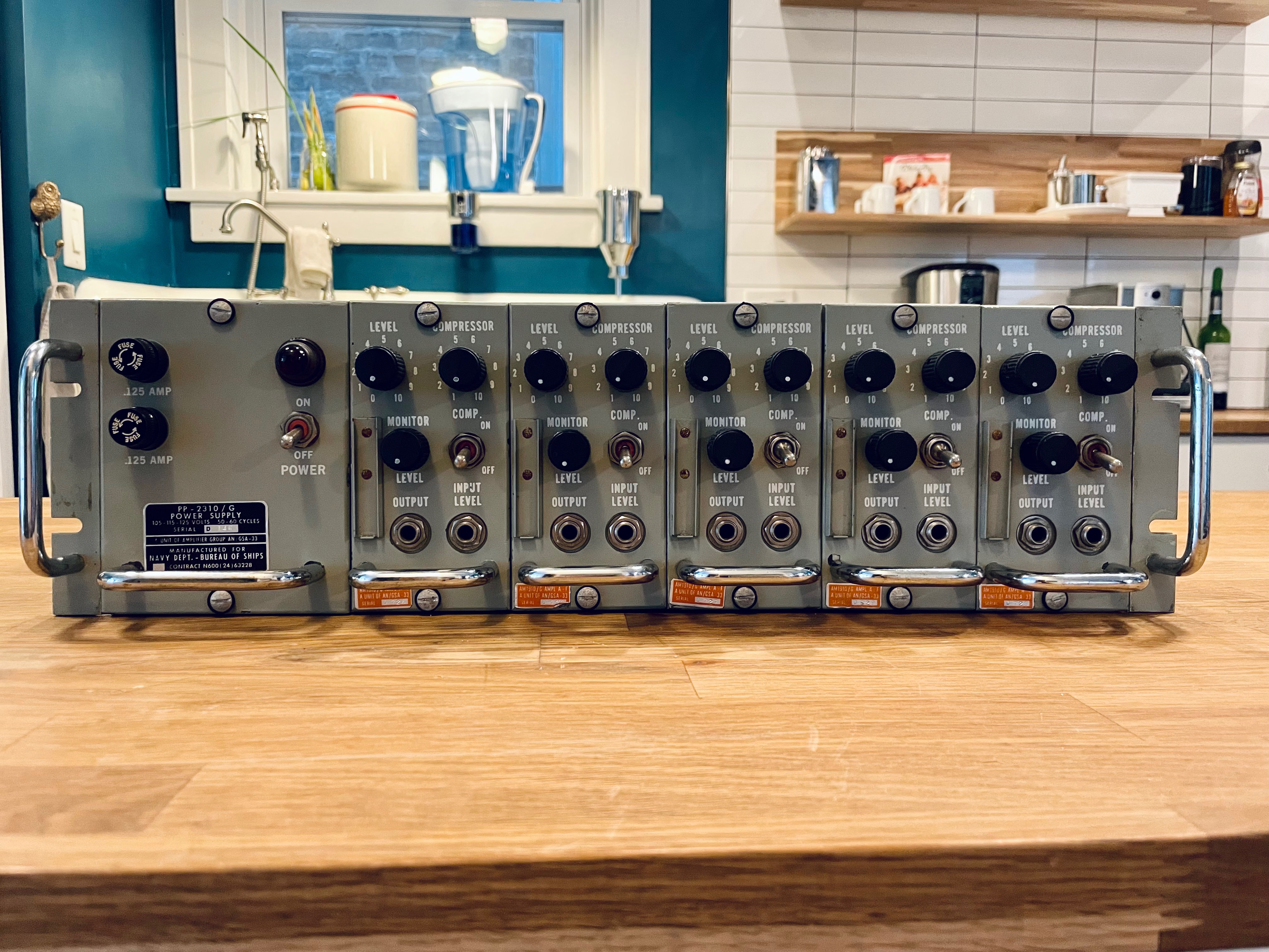
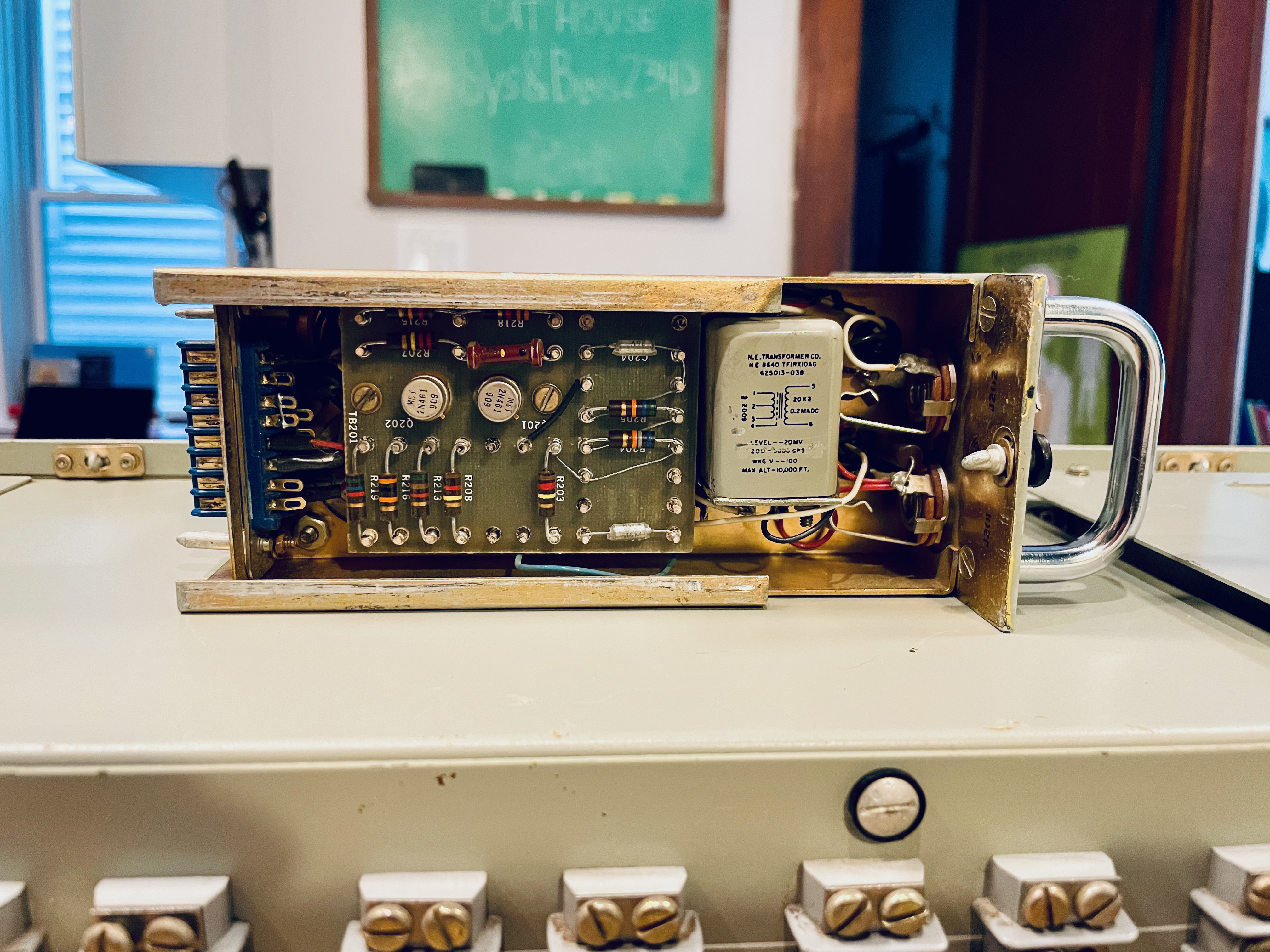
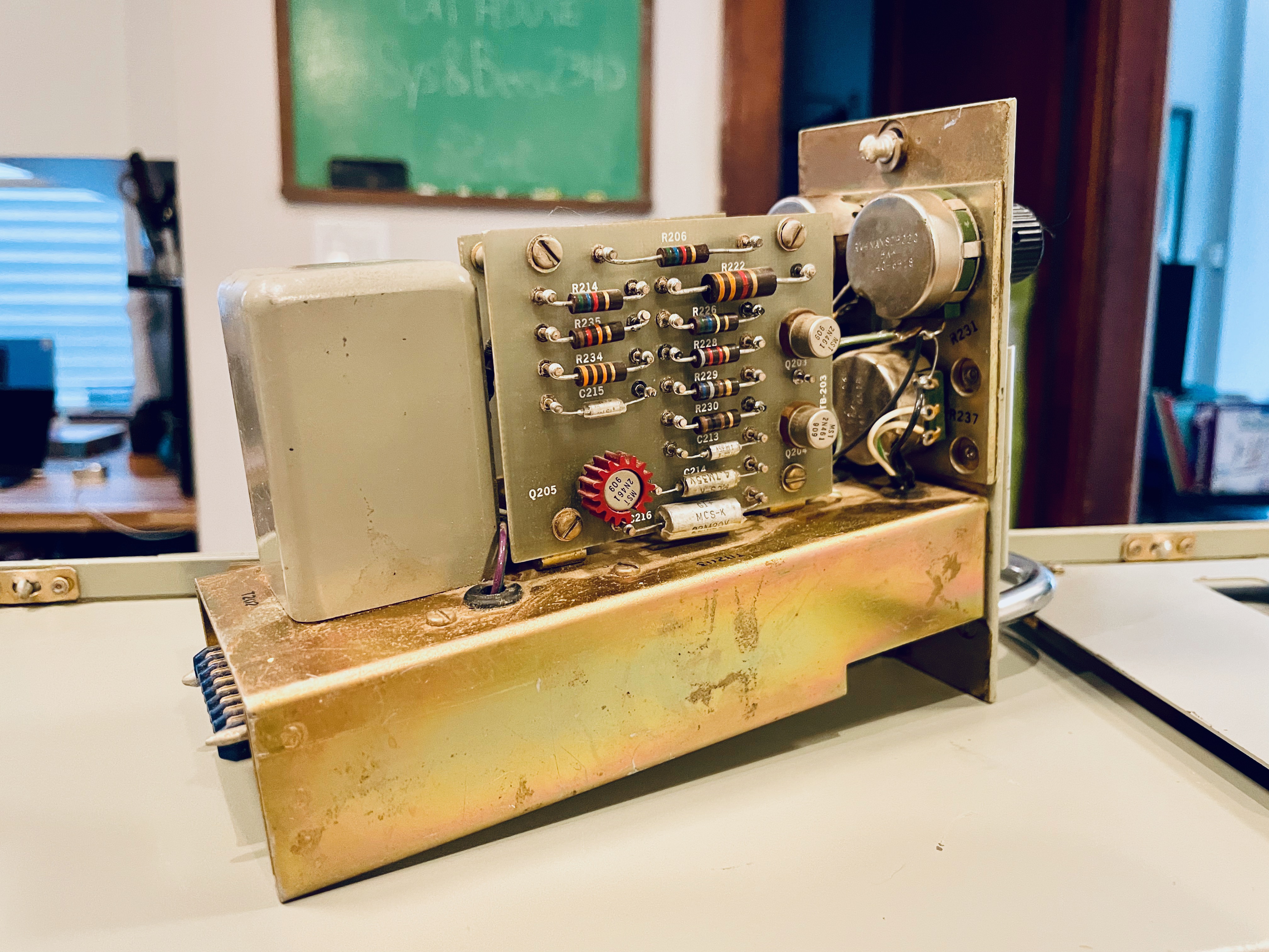
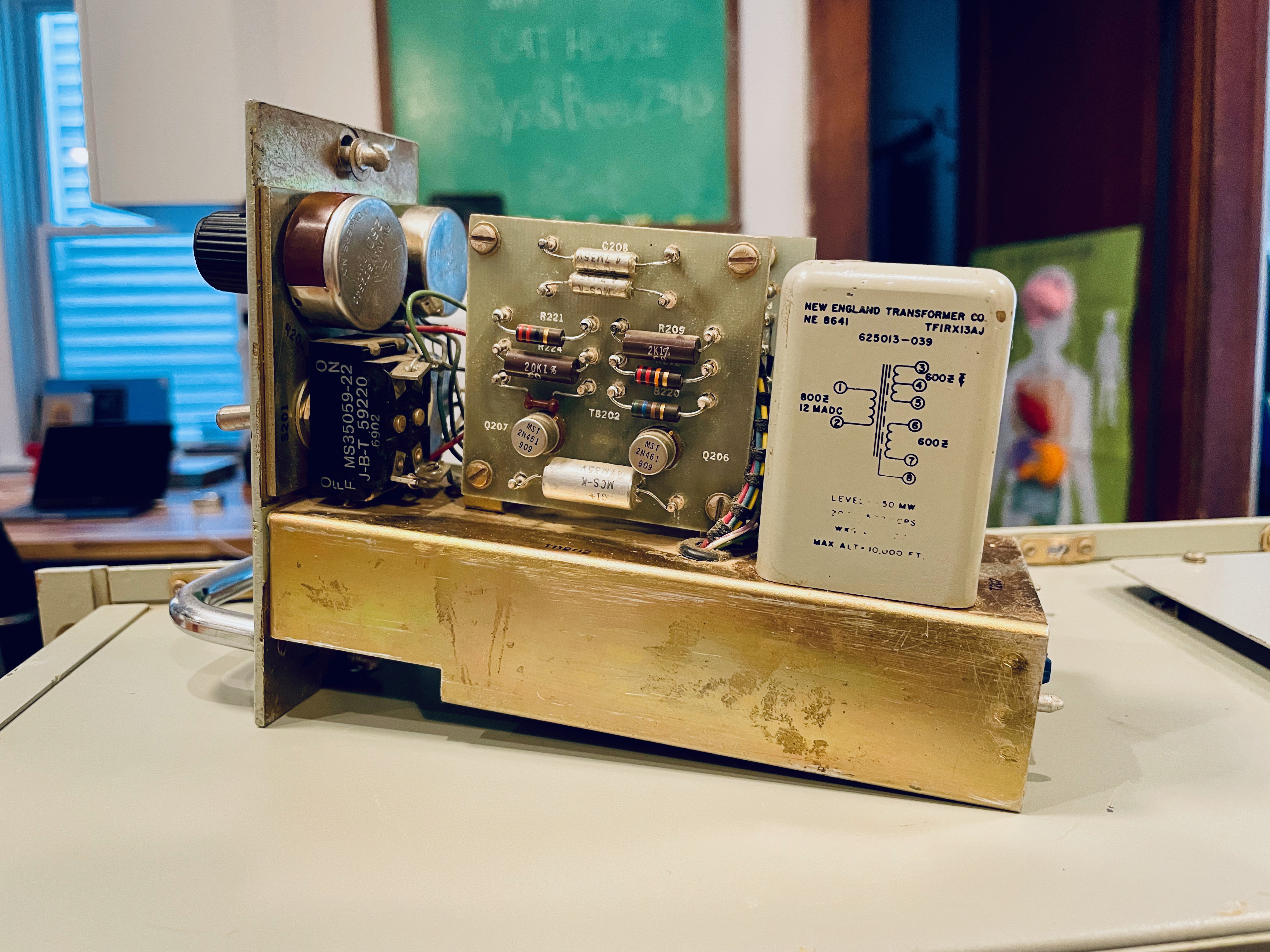
I'm starting work on a Melcor Navy Department - Bureau of Ships 5 compressor unit. From what I've read, these are from the early 1960s. My initial plan is the recap the unit, adjust frequency response and go from there. Looks like most, if not all the caps are Sprague mil-spec tantalum. I plan to replace the 3 capacitors in the power supply with electrolytic, but unsure if I should go through each unit and replace the tantalums as well.

Has anyone worked on these units before? or have a schematic?

There is a thread on groupdiy (link), but the schematic drawn there looks slightly different than my units.

Not sure how usable they will be for the studio, but figured I'd give them a go.

IMG-1589.jpg
IMG-1588.jpg

IMG-1587.jpg
IMG-1586.jpg
 
I plan to replace the 3 capacitors in the power supply with electrolytic, but unsure if I should go through each unit and replace the tantalums as well.
Some comments in the other thread indicate that some capacitors will need to be increased for bass extension.
Since the PSU is single-rail, there are less issues with polarity inversion at turn-on/turn-off, so the tants may not need to be replaced.
There is a thread on groupdiy (link), but the schematic drawn there looks slightly different than my units.
Well, it's good starting point for figuring out the differences.
 
I would recommend really looking into the capacitors on there before just tossing them out. Only specific aluminum electrolytic caps leak and dry out badly, primarily the can-style capacitors that have tabs on them (not the screw-terminal ones, those ones are actually perfectly sealed). If your compressor there is military, it's got military caps.

From here, those look like wet slug tantalums, and I've seen those in working equipment, and bought NOS stock from surplus and put it in my own projects, and they work just fine. Wet slug tantalums, as opposed to the dipped yellow or blue or orange tantalums, have self-healing properties that the latter doesn't, which is why they last so damn long, on top of the fact that they're hermetically glass sealed. Personally, I'd just check to make sure your germaniums don't have tin whiskers by checking for shorts between leads, which is actually a common problem with really old transistor radios. But if they're good, you're good.

Edit: Measure those resistors by clipping a lead and checking it. Humidity leaks into them over time and will make their resistance drift wildly. Check one, and if it's more than the rated tolerance out of spec, then you might just have to check all of them.
 
That is a very cool looking unit. I think it’s going to take more than changing capacitors to get the frequency response up. Those transformers are only rated to 3K maybe 5K frequency response, hard to read. I believe their for compressing voice transmission so I as to be heard during battle. Still A cool project.
 
I sold a rack of five earlier this year, kept a couple loose modules for later. The rack was all original and had a high noise floor and was clearly high passed. Definitely do all the 'lytics and upsize the audio caps.
They are supposed be be like solid-state Maxson/Tri-Tronics CAA/FAA, but I could not tell from the condition they were in. And yes, labeled freq response is not always equal to actual response.
You mentioned yours are Melcor (yes, THAT Melcor). They were also made by Stromberg-Carlson and at least a few others.
 
Thanks everyone for the insight and help! I did test the transformers outside the circuit and they are basically flat 20-20k. I've order some caps and will hopefully start working more on them in the next week or two.

Good call on checking resistors. I sometimes default to assume they working and good.

I'll try to provide updates as I work through them.
 
Just finished building a new power supply into the original power sled. This helped the noise floor quite a bit, although it’s still higher than I’d like.

diy-tubes.com kit with Triad power transformer.

I’m debating running 48V and adding 20db pads to each of the five modules to facilitate running them as mic preamps with compression or line level compressors. The two 1/4” jacks (Output & Input Level) on the front are more or less unnecessary and are the right amount of space for a pair of toggle switches.

I’ll try to keep the updates coming.

B6DECE54-C3B3-406D-8962-0F7FC5F9046F.jpegF914EB6A-3B0E-4C5F-86C2-6BBA14739205.jpeg6378C982-3F0B-496C-B631-11CB66CFB6F4.jpegD0453D6C-EE79-4427-AE15-27CDBC515FDD.jpeg
 
Hi members, I have a single unit of these though my input transformer is a bit different but same rating. I want to make a power supply for it. Looking at the schematics it's running at +25V and -30V? Can anyone confirm? What can I modify to extend the bandwidth of the unit?
 
Hi members, I have a single unit of these though my input transformer is a bit different but same rating. I want to make a power supply for it. Looking at the schematics it's running at +25V and -30V? Can anyone confirm?
As far as I can see, there is no justification for a positive rail. The point that shows +25 should be negative.
EDIT: After a more thorough look at the schemo it makes sense to have a positive voltage there. It takes very little current (less than 100uA), so should not be difficult to drive from the same xfmr as the main 30V rail.
What can I modify to extend the bandwidth of the unit?
There is nothing in the circuitry that limits significantly the HF response (except the transformers). Regarding LF, you may experiment with increasing C201, C209 and C215.
EDIT; I see that it's covered in the other thread.
 
Last edited:
Quick question for folks. I have two modules that are feeding back when the "Level" control is past roughly 12 o'clock. "Level" as I understand is basically the output level control for the output amp. I've tried replacing all of the resistors on that output board and dropped in known-good transistors, but the issue persists. This issue also occurs the same way no matter "Compressor" (input) level and even if the compressor is switched in or out.

Is there something else I should be looking at here? Let me know if you need more details to help troubleshoot.

GSA33 comp.JPG
 
Do you mean adding a 600 ohm resistor across the output? I have not, the other modules work fine and have better frequency response without a 600 ohm load resistor. I can try that to see if it make a different.
 
Do you mean adding a 600 ohm resistor across the output? I have not, the other modules work fine and have better frequency response without a 600 ohm load resistor. I can try that to see if it make a different.
I'm not saying it's the definite cure, but it may give indications to the origin of the problem.
 
Have you increase capacitance?

I was checking on extending bandwidth on my Tri-Tronics CAA/FAA, by replacing transformers on input / output. Another person had tried that on a forum and said the circuit became unstable. The restricted bandwidth was part of the reason for stabilization. His comment was it would need a redesign when opening up the bandwidth. Could just be an excuse but lm passing it on.

How do the ones that work sound. The tri-tronics sounds lowfi which is cool for trash & thrashed sound but not good for hifi IMO.
 

Latest posts

Back
Top