Well DB25 would be nice, as long as all you want is a to turn it into a converter.
You would have to do a new back panel, or cut the old back panel and screw on an overlay panel, because the current one is full. So you would have to remove some of the board mounted XLR outputs and have both the inputs and outputs on DB25.
No mount screws on the rear end of the PCB, entirely supported by the connectors, maybe just insulating spacers or find a place for a standoff.
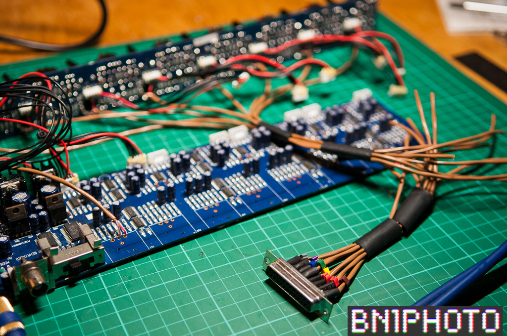
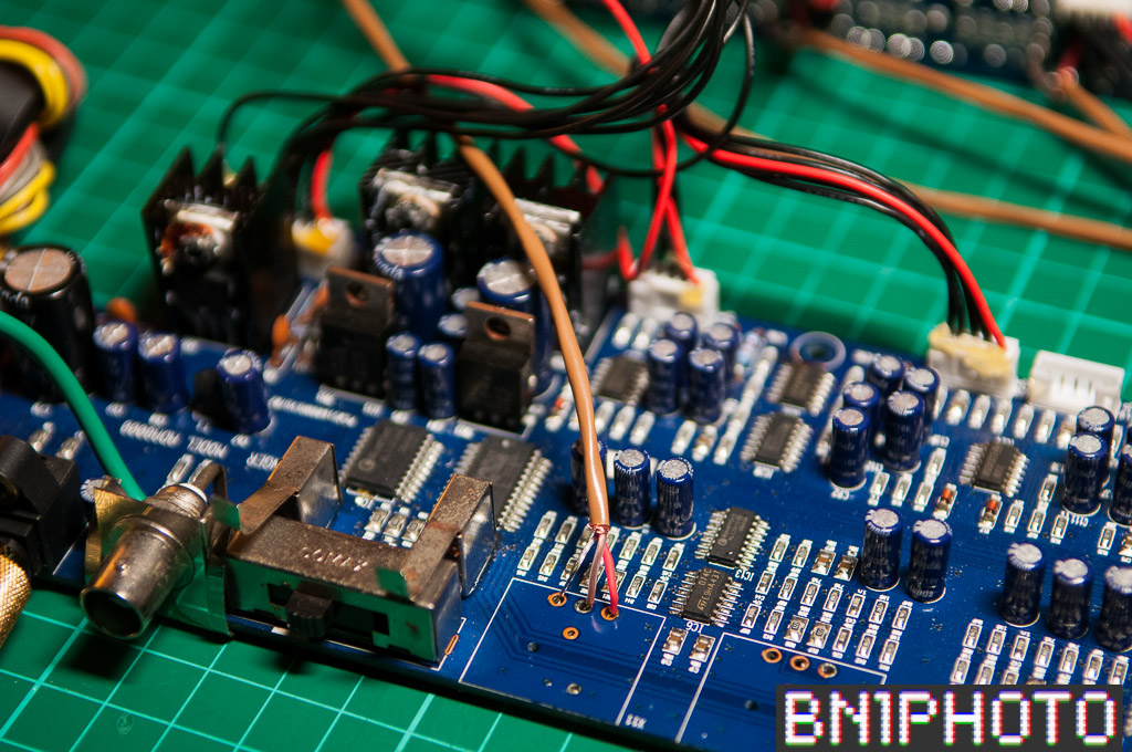
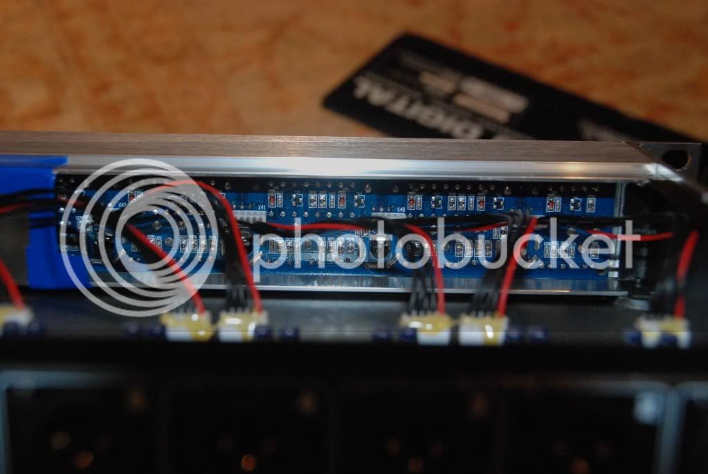
It would NOT be good to try to squeeze the DB25's in near the power connector, you can see in the pictures that you would interfere with the 5V regulators, and it would put signal very near power.
While you are cutting the back panel you could drill and vent the area near the (notoriously hot) 5V regulators, which would not be such a bad thing either.
As delivered the channel 8 end is noisier (Thus the extra shielding I taped in there in the pictures, I should have twisted the signal leads and rewired the connectors). I think this is radiated interference from the PSU being picked up by the gain stage.
The front panel PCB is glued in there, I never got it out, don't know how hard that would be.
Circuit issues... More difficult if you want to leave the front panel inputs in place ( the gain stage and phantom power circuit is in the front panel PCB) you would have to do some switching, or wire directly on to the front panel circuit board (if you could get it out of there). This is because the output of the gain stage output is low impedance, and I think would present very low impedance (500 ohms or less) to the DB25 inputs and possibly fight with them too. Not too sure about that.
The easier way to just make it a converter. No phantom power. No mic gain stage. You could just disconnect the front panel inputs at the pin headers (but leave the 2 LED signal and clip indicator wires). The 5 pin connectors on the board carry 3 pins of signal and 2 pins of 5V red/green LED and Signal indicator driven by the LM339 comparators.
So you could take out the gain stage (some folks say that it would be an improvement, but general consensus is that the gain stage is not so bad), and run those 3 wires from the connector to your DB25 (twist them), and you would:
1) Retain functioning green signal and red clip indicators.
2) Permanently disable the front panel connections.
3) Get a high impedance input directly to the TL074 (balanced) stage Note: You may want a rectifier bridge to the rails for static/phantom goof protection, and you may want to cap couple it to deal with dc on the inputs. The existing front panel pcb has the caps (for phantom) but not the bridge, but the TL074 may be more sensitive.
4) A side benefit is that you would be routing twisted wires away from the power and the gain would be external unaffected by the ADA8000 PSU. So the noise floor should drop some, at least on channel 7 and 8.
If you went that way, I think you could replace the whole front panel too. Just 8 red/green LED's and the master lock indicator led (circuitry appears to be on the main board, just the LED on the front PCB). (From a quick look at the schematic)
You could test most of this by pulling the top off, and connecting directly to one of the pin headers in the picture (they are hot glued down) and seeing how it worked. Pins 4 and 5 are the red/green indicator. There are nice complete schematics around for this thing.
Ian has some DB25 summing boards that would work for easily wiring up the connection either solder to pad or with a pin header (rather than directly crimping to the DB25, which in my opinion just asks for getting some pin phase inverted)
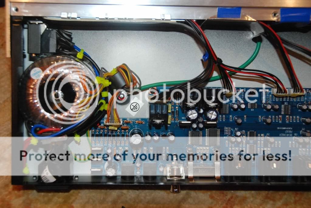
Here is the inside, from a long time ago:
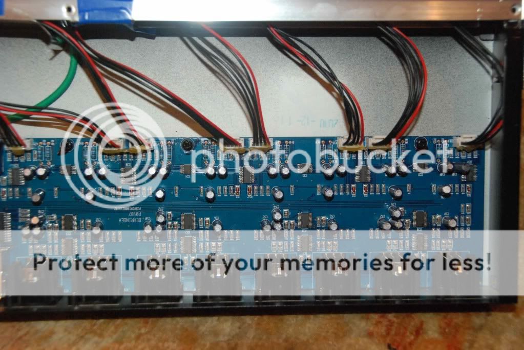
Back of the front panel PCB, glued in.


![Soldering Iron Kit, 120W LED Digital Advanced Solder Iron Soldering Gun kit, 110V Welding Tools, Smart Temperature Control [356℉-932℉], Extra 5pcs Tips, Auto Sleep, Temp Calibration, Orange](https://m.media-amazon.com/images/I/51sFKu9SdeL._SL500_.jpg)


")