Motown Direct Amplifier-inspired Preamp?

GroupDIY Audio Forum

Help Support GroupDIY Audio Forum:

This site may earn a commission from merchant affiliate links, including eBay, Amazon, and others.
FWIW, this page

There's also a top of chassis pic (I've brightened it since the can cap is difficult to make out in the original) :
Interesting take on the picture, sort of new perspective ... which makes me realise this is built on a PCB ... Makes sens from a manufacturing process point of view, but it's a bit sad, IMO. A cute little design likes this screams PTP to me :)
 
Last edited:
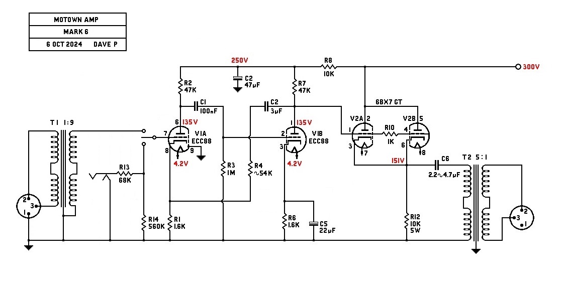
Dave's circuit is looking a lot better since i took out the Neve isolation transformer i was using to drive the input, flat to 100 K with no phase shift! My circuit starts to shift at about 10 K Hz, is flat to about 20 K Hz,

the square wave problem also disappeared after removal of the offending xfmr.

overall gain with the OPT strapped for 600 ohms is about 46.

that circuit i built has worse specs than Dave's but it clips a little nicer.

amps with feedback tend to clip in a harsh manner, but since they have more headroom, the clipping will probably never take place.
 

Attachments

  • sc2.JPG
    sc2.JPG
    239.9 KB
Last edited:
Thanks Brian!
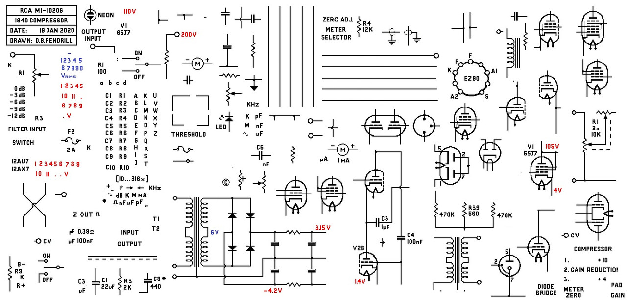
There is no app as such, you might notice the similarity to the original LA-2 schematic?
When I made an LA-2 back in 2008, I copied the schematic into MS Paint and after tidying it up, I have been using it ever since.

I just copy and paste, its quite therapeutic!
best
DaveP
 
There is no app as such, you might notice the similarity to the original LA-2 schematic?
When I made an LA-2 back in 2008, I copied the schematic into MS Paint and after tidying it up, I have been using it ever since.
Same technique I was using for the schematics at the start of the thread (albeit with Photoshop and a Pultec diagram) and I agree, there's just something relaxing about it!
 
CJ has made the first practical version of this circuit with the tubes he had "in his sock drawer", being a 6N1P.
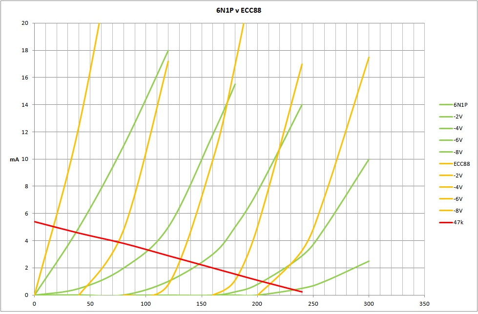
I made this combined chart to show the difference in the working point when using the 6N1P instead of the ECC88.

The green traces are the 6N1P @ OV, -2V, -4V, -6V and -8V, the orange traces are the same voltages for the ECC88.
The red line is the 47k load line.
The 6N1P has very curved lines down there compared to the ECC88. I think it is also more linear around the -4V working point.
This may make it more transparent, but maybe the 6N1P may have more "tone"?
best
DaveP
 
Last edited:

Latest posts

Back
Top