Motown Direct Amplifier-inspired Preamp?

GroupDIY Audio Forum

Help Support GroupDIY Audio Forum:

This site may earn a commission from merchant affiliate links, including eBay, Amazon, and others.
I think we discussed earlier that when paralleled the gm doubles, rp halves and mu remains unchanged.
Cheers
Ian
That is what I have done Ian, but the exercise shows how far reality differs from the published tube specs and how important it is to calculate the figures in the actual circuit.
best
DaveP
 
I agree. Published specs seem to be designed to show the maximum gm achievable without melting the tube and bear no relation to the values actually achieved under normal circuit conditions.

Cheers

Ian
 
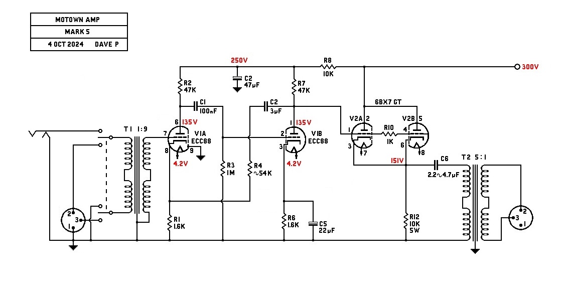
>> Shouldn't your schematic also be showing a 1/4-inch instrument input jack as well as a switch toggling between it and the XLR? Just wondering.....

>> Do you have any suggested recommendations as to what both T1 and T2 "could/might" be? With my knowing who makes them and what their Part Numbers are, I could layout a series of hole cutouts on the top of the chassis which would then be used to accommodate any one of them.

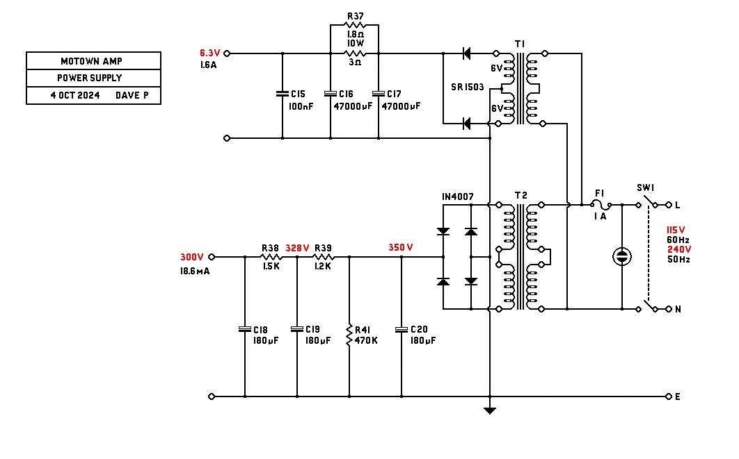
>> Is there an accompanying power-supply schematic for this circuit somewhere?

>> Are all of the resistors 1/4-Watt (other than R12)? Or, do any of the resistors need to be 1/2-Watt?

I can draw a jack circuit and switch if it will help.

For T1 I would use a mumetal case 600:50k from RS https://uk.rs-online.com/web/p/audio-transformers/2106352?gb=s, but there must be others that are similar. For T2 I would use a 2.5W edcor 15k:600 but people may turn their noses up at that! This thread has discussed the transformers in some detail. Look Midnight, trying to get all the mounting holes predicted may not be wise, because that chassis is small and you may have to move the transformers around to avoid hum pick up. Look how they mounted that choke for instance.

I can draw a suitable power supply but I can't predict the performance of your chosen power transformer, adjustments will probably be necessary.

I only use 0.75W metal film resistors for ruggedness and lowest noise.
best
DaveP
 
Power Supply:

The power transformer secondary is assumed to be 250V and depending on the regulation, should give around 350V after the bridge.
best
DaveP
 
I can draw a jack circuit and switch if it will help.

For T1 I would use a mumetal case 600:50k from RS https://uk.rs-online.com/web/p/audio-transformers/2106352?gb=s, but there must be others that are similar. For T2 I would use a 2.5W edcor 15k:600 but people may turn their noses up at that! This thread has discussed the transformers in some detail. Look Midnight, trying to get all the mounting holes predicted may not be wise, because that chassis is small and you may have to move the transformers around to avoid hum pick up. Look how they mounted that choke for instance.

I can draw a suitable power supply but I can't predict the performance of your chosen power transformer, adjustments will probably be necessary.

I only use 0.75W metal film resistors for ruggedness and lowest noise.
best
DaveP
>> DaveP: -- THANKS SO MUCH!!! The information you have provided in your response here is all good information to know just in a general sense. But, perhaps you are mistaken or perhaps what I have been doing and saying within my comments hasn't been very apparent or clear. Let me explain.....

The efforts I have put forth and have shown within my comments in this thread -- HAVEN'T BEEN FOR ME!!! -- My creating a chassis design and requesting a more complete schematic, etc. -- ARE FOR THE MEMBERS OF THIS FORUM!!! NOT ME!!! -- In other words, the members of this forum who would like to build this project and who also may not be so mechanically-inclined to design and layout a chassis (as one "certain member" in this thread has personally admitted that they are "mechanically all thumbs"), could simply use my eventual mechanical detail fabrication drawing and/or perhaps the 3D CAD-file I will generate, to have their own chassis fabricated in such a manner that it will actually work out well for them. That's all.....

[you may have to move the transformers around to avoid hum pick up] -- Then, how about possibly using a steel chassis and/or also including a steel shield over the transformers? Would an aluminum chassis with a steel shield placed over the two transformers work well enough? Doing something like that is easy enough for me to do and to also include with the chassis design.

[I can't predict the performance of your chosen power transformer] -- Since I am not a "Circuit Designer" type of person in order to know what happens electronically but, isn't there some kind of "voltage-range tolerance", where a few volts either side of some ideal voltage still allows the circuit to operate well enough? Meaning, if the 300V in someone's build actually ends up being only 296V, that the circuit will sound just awful? I find something like that rather hard to believe. But, what do I know?

[I only use 0.75W metal film resistors for ruggedness and lowest noise] -- There are far more resistor values available in a 1-Watt 1% Metal-Film package than there are for a 3/4-Watt package.

/
 
[you may have to move the transformers around to avoid hum pick up] -- Then, how about possibly using a steel chassis and/or also including a steel shield over the transformers? Would an aluminum chassis with a steel shield placed over the two transformers work well enough? Doing something like that is easy enough for me to do and to also include with the chassis design.

[I can't predict the performance of your chosen power transformer] -- Since I am not a "Circuit Designer" type of person in order to know what happens electronically but, isn't there some kind of "voltage-range tolerance", where a few volts either side of some ideal voltage still allows the circuit to operate well enough? Meaning, if the 300V in someone's build actually ends up being only 296V, that the circuit will sound just awful? I find something like that rather hard to believe. But, what do I know?

[I only use 0.75W metal film resistors for ruggedness and lowest noise] -- There are far more resistor values available in a 1-Watt 1% Metal-Film package than there are for a 3/4-Watt package.
An aluminium chassis is usually best because it does not conduct a magnetic field, steel shields can help.
4 or 5 V either way will not matter but 10 or 15V will shift the working point.
1W metal film are even better.

Thanks for explaining
best
DaveP
 
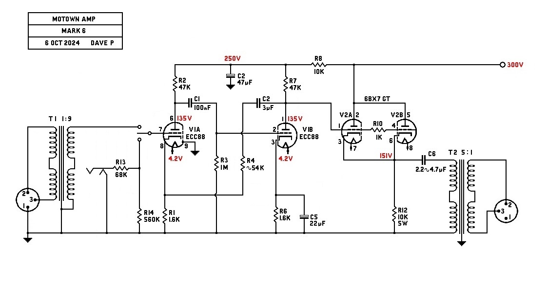
So wouldn’t you want the mic / DI input switching be done after the 600 ohm input transformer, where the input switch would select either the mic transformer secondary for mic input, or the 1/4” DI input and send that to the grid of the first tube?
 
So wouldn’t you want the mic / DI input switching be done after the 600 ohm input transformer, where the input switch would select either the mic transformer secondary for mic input, or the 1/4” DI input and send that to the grid of the first tube?
That's how I also thought things would be done as well.

[the 1/4” DI input and send that to the grid of the first tube?] -- Would this be a "direct straight-in" connection? Or, would there also need to be some kind of a DC-blocking capacitor and an input loading resistor, too?

/
 
[This is what I should have done the first time!] -- It's 5:45 AM on a Sunday morning as I write this and just moments ago I have ordered 2 -- 6BX7GT vacuum-tubes from a place here in the U.S. that advertises that they have 1,000,000+ vacuum-tubes in stock!!!

Strangely enough, I was originally really only ordering some "electrolytic capacitor mounting clamps" so I could physically measure them in order to create a 3D CAD-model of it, but this supplier has a minimum order threshold, so I figured I might as well purchase some tubes just to meet their minimum. Did someone once say that DIY is an expensive hobby?

So.....plugging-in either an electric guitar or the output of a synthesizer into the "instrument input jack" doesn't need either a decoupling capacitor "just in case" or a resistor to ground to set some kind of "input loading impedance" or something like that? Circuit design is not my forte', but I thought that's how things are done on the inputs of vacuum-tubes. But.....what do I know? You're the expert!!!

And, finally.....can your power-supply schematic handle 2-Channels of circuitry? Or, just the single-channel as is shown above?

THANKS!!!

(This message is certified to be "Text-based Graphically Expression-Free).

/
 
So.....plugging-in either an electric guitar or the output of a synthesizer into the "instrument input jack" doesn't need either a decoupling capacitor "just in case" or a resistor to ground to set some kind of "input loading impedance" or something like that?
The input is standard Fender, see CJ's project https://groupdiy.com/threads/motown-direct-box-diy.88733/
Transistor gear seems to go in for input caps more than tube gear.
The power supply will be OK if you halve the dropper resistors and the transformer is up to the load. (heater too)
18.6*2=37.2mA. .0372A x 250V =9.3VA a very small HT transformer, so go for the next one available.
3.2A x 6.3V =20VA, so the heater factor will dominate your choice.
best
DaveP
Got it!!!.....

/
 
Last edited:
ok i built Dave's circuit, did not get the output transformer installed yet,

i accidently used a Sylvania 12AX7a for the preamp tube, did not see the ecc 88, i will try that next,

so far it looks good! much more headroom than my circuit,

unity gain on the first stage with the feedback so no worries about overdriving that stage,

gain without output xfmr is 30,

i have a resistor between the power supply B+ on the preamp tube so that's why the B+ is not the same,
 

Attachments

  • dave1.png
    dave1.png
    231.8 KB
the sine wave looks real good for all input levels, but there is quite a bit of ringing with the sq wave,

that might be corrected with a cap somewhere,

sine, square and clip shots>
 

Attachments

  • dave3.JPG
    dave3.JPG
    381.7 KB
  • dave2.JPG
    dave2.JPG
    382.8 KB
  • dave4.JPG
    dave4.JPG
    390 KB
Found a 6N1P. (6N1H) in the junk drawer, this circuit sound very nice! Very clear, will plot the freqs, the top end could be tweaked by a cap across that feedback resistor like the Telefunken stuff,

The preamp tube draws more current than the 12AY7 so the power supply resistors will need to be brought down a bit to get the voltages back up,

Not a lot of coloring, just a clean preamp.
 
Nice work CJ. (y)
I think the 6N1P is quite close to an ECC88, you could also try a 6BK7-B or a 12AV7.
The ringing is often from the IPT, may need 100pF? and 50k? in series across the secondary?
best
DaveP
 
Back
Top