My 603 Royer Mod

GroupDIY Audio Forum

Help Support GroupDIY Audio Forum:

This site may earn a commission from merchant affiliate links, including eBay, Amazon, and others.

Enchilada

Well-known member
Joined
Aug 24, 2011
Messages
323
Location
Australia
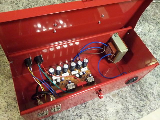
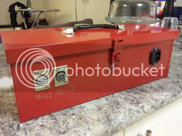
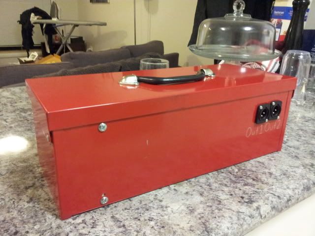
I finally got 603 Royer mod all soldered together and in a box, a toolbox to be specific! The box only set me back $10! I'll be heading out to the studio to test them out soon, I might A/B them next to my Gus modded 603s in case anyone's already done the gus mod and is considering going full blown Royer.

All I have to do before I'm 100% done is sort out the hum from the power transformer.

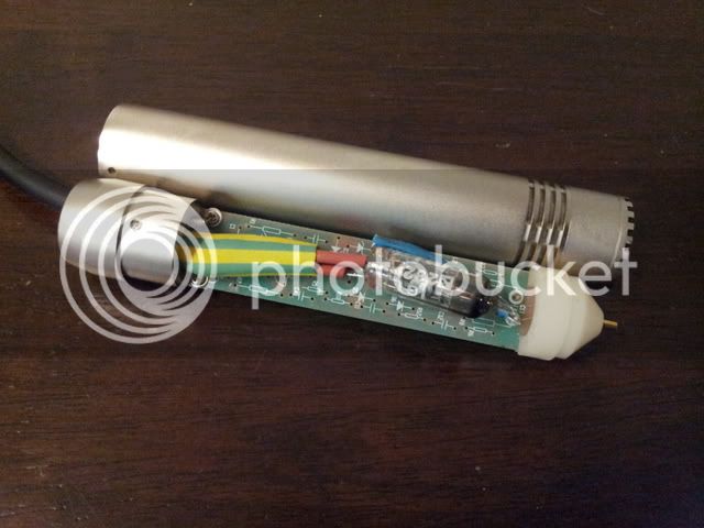
As a side note, I would definitely recommend this build for everyone who is interested in mics or mic modding. Although this is called the "Royer Mod" I think of it more as a build because you're basically building a microphone from scratch. I learnt a lot from this project especially since this is the first time I've built something by reading the schematic and not by populating someone else's PCB layout e.g. my Gyraf GSSL and my G7.

20120512_190321-1.jpg

20120512_200417.jpg

20120512_191444.jpg

20120512_191458.jpg
 
Love the PSU case! Very appropriate for these tools.
Looks like you might have room to work out a storage shelf or something to keep the mic's and cables in there too.

Also interested to see what you think of the comparison.

Cheers,
jb
 
Lol, that's exactly what I've been doing. I keep the mics, cables and power cable in there.

I haven't quite gotten them working yet. Voltages are perfect but I wired the transformers incorrectly. I think I've fixed it now. As soon as I get them going I'll A/B them with Gus modded 603. I now have two of each so I might record drum overheads and acoustic guitar.
 
I ask this question every time:

For the XLR's do you use a punch or a stepped bit or something else? I'm trying to decide which to get, and I'm getting as many opinions as I can...

Thanks!
 
for xlr's I am a huge fan of using uni-bits aka step bits.  It can sometimes be cheaper then the punch and gives you options for other things like pots 1/4 jacks, etc, etc.

 
just a heads up. (if it already occurred to you disregard) your enclosore(tool box) is painted inside and out. you'll have to scrape away some paint in order to make contact with the enclosure to ground.
8) 8) 8) 8) 8) 8)
 
Did occur to me, I connected the ground to a screw on the power socket and tested that is has a good connection between all other ground points. Definitely a great point to bring up if anyone else is looking to use a toolbox as an enclosure.

That said though, grounding I think is still a massive issue with this project. I've connected the ground wire from the mains to the case and the xlr outs but not yet to the xlr ins. I also haven't connected the ground of the circuit board to the mains ground and I'm thinking this might be my problem but I haven't done anything about it just yet.

Basically the issue I'm having is a tremendous amount of hum. Although I am getting a good signal from both mics and a great tone.
 
Yea, I'm battling hum in a mic as well today. But just from looking at your layout, could be that you have the mic transformers on the smae PCB as your power supplies, but more importantly you have that honkin transformer next to everything...
Try the "power off" trick. If you power off and hum disappears in the few seconds you can still hear, its probably coming from the power transformer/power supply.
Also i've noticed grounds can be touchy..
What do you mean gounds aren't connected to xlr ins? Also you should only have the audio ground connected to chassis ground at one spot and then connect all the pin 1s on your output XLRS just to chassis.
 
You know, I've always wondered.... Whether it's best to have the complete head amp floating with respect to the body/chassis and a single 0v ref conductor terminating in the psu @ the negative of the last filter cap with the body connected to shield and chassis star point. How about a dedicated heater return if that's separate from cathode?

Seems like a lot of them connect 0v in the mic body to mic-body-chassis and have both shield and a conductor back to psu and are fine...

Does it matter?

 
OK, I've sorted out my grounding issues so now when the power is off there is absolutely no hum, buzz or noise of any kind. As soon as I flick the switch it's back. Reorienting the board with the audio transformers further away from the power transformer helped a lot although it is still REALLY noticeable.

Has anyone here ever used shielding cans in transformers? Do they work well? I'm thinking of buying a pair of these cans because they suit my transformers:
http://au.element14.com/jsp/search/productdetail.jsp?SKU=1172345&ICID=ap-1172345-pr

If that isn't going to make much difference, the only solution I can see is to put the transformer into a separate box.
 
I just build a royer mod, and I had a transformer like yours...the square shape (not sure of their technical term) and was experiencing buzz, I switched to a toroidal transformer and that helped my buzz *alot*. Also making sure the heaters ground and b+ ground are referenced (connected) to each-other helped a lot. But I'm pretty sure if your using the royer schematic that shouldn't be a problem.
Also not sure how close your microphone transformers are to the AC/diodes section on your protoboards, but that could potentially be a problem also. And are you grounding the shields on your microphone transformers? if so where? They probably would like a separate star ground to chassis.

Goodluck!
-Abe

Also on a side note, I found a little mic in transformer, and it was just the right size to fit into an MXL 441 I have around (basically a black 603) So wired it backwards and used the output section of the km84 circuit and worked better than expected. Smoother, rounder sound than stock. And I've been on a tube microphone kick for a while, a direct result, i think of not wanting to wire up phantom power into my homebrew mic preamps, but now I'm craving some solid state clarity. Recorded some drums a bit back with a pari of 991 pencils mics with the "gus" mod. Basically changing the signal capacitors, then I took the oscillation HV circuit out  (it smoothed up the sound) and also replaced the FET with the ones being used in the u87s (2n3819) and re-biased it.
 
abechap024 said:
Also making sure the heaters ground and b+ ground are referenced (connected) to each-other helped a lot

...

And are you grounding the shields on your microphone transformers? if so where?
The heater is grounded by grounding pin 4 in the case. I've just seen on the original schematic that pins 5 and 7 of the tube, before pin 2 of the mic cable, appear to go to ground but I'm not sure. If it were grounded wouldn't the line under 5,7 connect to pin 3's ground in the schematic? Wouldn't grounding pin 2 also short pins 2, 3 and and 4 seeing as pin 4 is also grounded?  ???

Yep, I did ground the shields on the mic transformers. to pin 1 of the XLR out, then to the case.
 

Attachments

  • Royer mic.png
    Royer mic.png
    207.2 KB
What are the current and voltage ratings for the power supply transformer you used?

I count 14 electrolytic caps in the picture did you build two supplies and wire them in parallel with one  transformer?

For better help you should post a wiring drawing of how the supply is wired and where the grounds go.


0dbfs said:
You know, I've always wondered.... Whether it's best to have the complete head amp floating with respect to the body/chassis and a single 0v ref conductor terminating in the psu @ the negative of the last filter cap with the body connected to shield and chassis star point. How about a dedicated heater return if that's separate from cathode?

Seems like a lot of them connect 0v in the mic body to mic-body-chassis and have both shield and a conductor back to psu and are fine...

Does it matter?

I did that by accident on my first Royer build. (The 2001 mod, with the transformer in the mic, not the cathode follower version here.)

The PSU grounds float above the chassis ground. I'm not sure if that is *safe* but I don't have any hum.
 
Looking at your pictures, I don't see twisted pairs or shielding going from the board to your XLR output connectors. I would address that first.
 
Back
Top