My circuit of low voltage audio amplifier clips on 8 ohm loads

GroupDIY Audio Forum

Help Support GroupDIY Audio Forum:

This site may earn a commission from merchant affiliate links, including eBay, Amazon, and others.

Leonardori

New member
Joined
Jul 28, 2016
Messages
2
Hello, I want to post my project here .I hope you can correct me if there are mistakes. And I hope my experience can give you a little help . 
Exposition time:
One could call me a freshman in electronics and I just designed my first little audio amplifier for headphones. (Pocket design, I want to be able to drive 4 headphone pairs from a single source) Here's the schematic, so you guys know what I'm talking about:
(Without power supply (9V bat) and single channel)
Qle1V7i.png

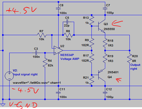
Ofc, 4 headphones draw a lot of current, which is why I need a proper output stage. Up to 200mA to be precise. The current design I made uses 2N5551 and 2N5401 transistors but their DC current gain is horrible (<10) which causes the OPA to overdrive. I don't want to much load on the OPA as well (max 20mA). A higher input voltage is out of question.
Therefor I need better output transistors (Q3 & Q4) which provide a higher current gain but also are capable of switching fast enough for audio signals. They should be cheap and small. I don't know that much components and the market out there is just a jungle of different parts.
The question:
Is it possible to compensate for the clipping with different output transistors? The circuit behaves great on 32 ohm but a lower load impedance wrecks it. I'm also open for darlington array solutions.
*EDIT: I can't use SMD parts. I need through hole packages.
**EDIT: Juuuust figured! This OPA is not even able to supply 20mA, because R9 & R17 are to large. In that case, a darlington setup with the current transistors could work, I just have to lower those resistors. Will keep you guys updated. ;)
________________________________________
Solution: There's more than one solution to this problem:
1. Use a different OP amp which can drive the transistors rail to rail (see accepted answer). This only works if the 2N5551 and 2N5401 output transistors are configured in a darlington setup. However, the OPA used in this circuit almost drives rail to rail, already. (+-4V on the output)
2. Other output transistors with a better gain. 8550 (PNP) and 8050 (NPN) behave greatly for this application, they still need a darlington setup, though. (Special thanks to Spehro Pefhany)
3. Increase the supply voltage. This works like a treat, IF you're actually able to do so. Sadly, I am not in my setup.
4. Replace the output stage with a "diamond buffer circuit". It performs well in the simulation, did not test it on the bread board, yet. But it's nature of a voltage follower driving the push/pull transistors decreases the total swing of the op-amp, which results in better slew rates and therefor also frequency response of the circuit. Thanks to ioplex for adding this in.
My Solution:
I kept the OPA and used a darlington setup on the output. On my previous tests I forgot to modify the voltage divider to adjust the offset voltage between both transistors. I fixed that and now the circuit works. No clipping even on the worst input signals, that's what I wanted. Tests with my bench supply show that it actually operates down to +-3V which is great if you consider the voltage drop on the battery as it decharges over time. This is just the first design, I will change some things in the future. It is pretty clear that this is not the best setup and that I'm not using the best components for it. Design goals, however, were low component costs and supply voltage. And these are met with a decent performance of the circuit. It does sound gorgeous, feel free to try it yourself! :)
Thanks to everyone for the help I learned a lot through this project.
Here is the new schematic (2N5550 is a 2N5551):All the components were from :http://www.kynix.com/
Zo3zYfV.png

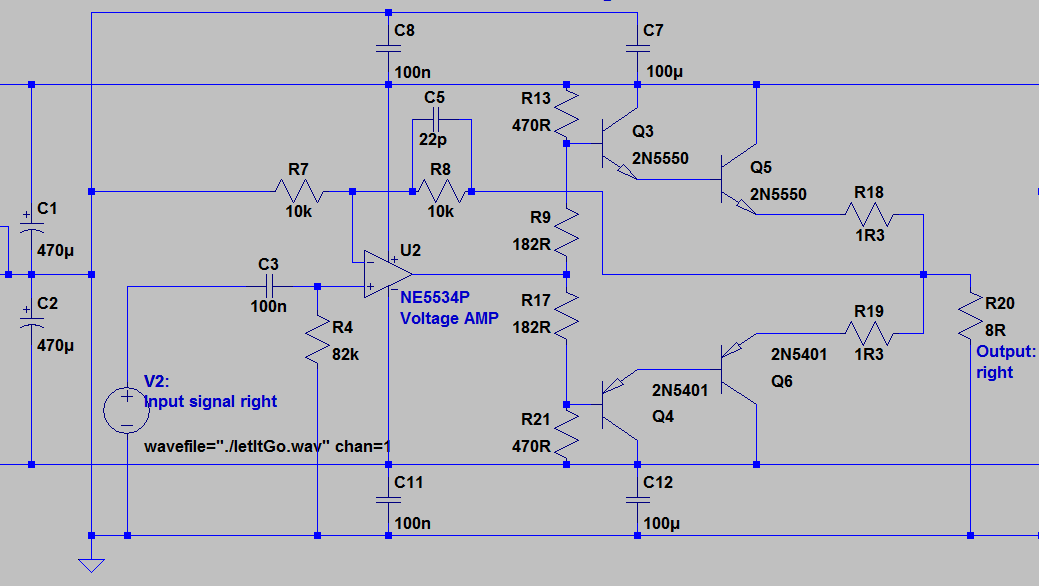
PS: What's no in this schematic is the compensation cap on the COMP - COMP/BAL pins of this particular op-amp. It's 47pF but LT-Spice has no proper symbol for the NE5534P.
 
Standard transistors like TIP41C/TIP42C should perfectly do the job.
You could improve the headroom of this crcuit by bootstrapping R13 and R31.
 

Attachments

  • bootstrap.jpg
    bootstrap.jpg
    91.2 KB · Views: 22
With only 9V total (+/- 4.5V)  the op amp will not swing rail to rail, and you will lose a few diode drops from the transistor junctions so output voltage swing will not be the full supply..

How are you forcing the 9V supply to split equally as +/- 4.5V?

Headphones are often >> 8 ohm but some can be that low.

+1 to bootstrap. Putting backwards connected diodes across R3 and R17 can increase drive current.

JR
 
Welcome.

Opamp with booster to drive speaker-load. I was there 40 years ago.

If you want an Answer instead of an Adventure: LM386 (or LM380 if you can). Pre-made solution for speaker driving. Use all the application sheet details, the R-C on the output can be critical. 38 years ago, after playing with opamp boosters, I plopped a couple '386 in a vital headphone driver and everybody was happy.

However, I see you like the adventure.

If you can afford the money and TIME, Self's and Cordell's Audio Power Amp books are must-reads. However they start above your current level. And with more ponder-time on me, it still took weeks to first-read Self and months to get through Cordell. Sloan also has a book which may be a better starting point.

> Up to 200mA to be precise.

Never be "precise" driving speakers (phones). Voice coil impedance varies widely. Users WILL push to clipping. With +/-4.5V supply you would like to get 4V peak output. 4V/8r looks like 500mA. "8r" speakers can be 6r in mid-bass; "32r" headphones are often cheated toward 20r to suck more out of an iPod. "500mA for-sure and maybe 1,000mA?" is as precise as is warranted.

> 2N5401 ...gain is <10....

I see a higher number on the sheet but at 100mA, and falling fast. Yes the sheet boasts of "600mA" but that appears to be a "blow up" spec. Current gain is falling fast above 50mA. These are not good choices for a "500mA-1000mA", or even 200mA, problem.

Generally you want the transistor "max" rating to be MUCH more than your intended current. Discount the maker's extreme-case rating, leave a large safety margin. Current gain is usually way down at the Max rating.

The opamp will "see" the load impedance multiplied by the in-circuit current gain of the booster. Taking hFE=20 and ignoring stray paths, 8 Ohms times 20 shows about 160 Ohms to the opamp. Using your second plan with R13 R21 = 470, that is another 235r to drive. 160||235= 95 Ohm load on the opamp. The '5534 is targeted for 600 Ohm, will pull 300 Ohms even at +/-15V, and lower at lower voltage. But 95 Ohms is way below its comfort zone.

You want more current gain in the buffer. A nice round 100 puts the opamp load near 800 ohms, and it will be much happier, and small spec-slips won't put it far below 600 Ohms.

These are "small" (TO-92) transistors which may be a mistake. 2N3904 gives gain of 100-300 but at 10mA, falling to 10-30 at the maximum 200mA current.

Abbey's suggestion of TIP41 is a 6 Amp part, which smells like overkill. But 1000mA or 1A peak current is not-so-much discount of a 6A max. Data suggests current gain may be 100 for 50mA-500mA falling slightly at 1000mA, so is about what you want. TIP parts have been MASS production for all these 40 years and should be readily available at good price.

(Note that A B C suffix denotes maximum voltage. I remember when this made a real price difference. But even the 60V "A" part is ample for a 9V job. Abbey typed "C" which is a 100V part. They may all be the same price now and small vendors should only stock "C" which covers A and B jobs.)

Now, power. 4V peak in 8 Ohms is 1 Watt RMS out. Rule of blunt-thumb for class-B sine audio is amplifier dissipation is 1/2 of output power. So you have 0.5W of heat in 2 transistors, 0.25W each. The TO-92 packages are good for 300mW (0.3W), tho some newer specs show 600mW. It is unwise to run a transistor so close to its dissipation rating, it will run HOT. Die young, also bias drifts.

Set up your sim with your R9 R15 bias resistors, DC analysis. Run default and note the transistor current. Now go into SPICE options and change the simulation temperature to 75 deg C (50 deg C rise over default). Run, and note the new transistor current. It will be WAY up. Transistor Vbe drops with heat. Resistor drop does not. While SPICE won't tell you, the new higher current will force the transistor hotter, drop its Vbe, raise current more, "thermal runaway".

R9 R15 should be diodes! Diode drop nearly tracks Vbe drop. Look at a million power amplifiers. Non-simple designs may use a transistor Vbe multiplier, same thing but fancy (trimmable).

> not even able to supply 20mA, because R9 & R17 are to large

Wrong thinking. ALL transistor base current must come from R13 R21. Yes, when that runs out, opamp output will shift further, reverse the direction of voltage drop in R9 (R17), and pull more. But such a large (~~1.2V) sudden jump of voltage is not good for the audio. It can't happen instantly, and the opamp has to recover from this large leap. Also two 1.2V jumps within a 9V total budget looms large.

Abbey's bootstrap will help, but adds loading on the output which hFE-reflects back to the opamp.

Darlingtons and other compounds do get LOTS more current gain, but generally at the cost of stacking-up Vbe drops. Your second Darlington plan seems to lose half of total battery voltage in Vbe biases.

You seem to be running class A. This is not necessary. And certainly not wise for 9V battery operation! Pick your emitter resistors 1/5th to 1/20th of the load impedance (you must first get temperature-stable bias!!). Bias for 0.030V-0.100V idle drop in emitter resistors. This near-B bias works in millions of audio power amps (also nearly every chip opamp).

I suspect this "+/-4.5V" is really a single supply. You will have trouble if you use this 9V supply to power single-9V circuits and try to connect the audio paths. As JR says, supply splitter design is an important detail. My smoke-filled experience says "beginners" should Capacitor-Couple outputs. Experimental designs are prone to come-up with the nominally-Zero output at a supply rail. 4V DC will fry many headphones in a few seconds. With cap-coupled output the voltage across the 'phone will always settle to zero. Cap-output loudspeaker amps fell out of favor decades ago, but you can find sketches of such designs to study. (The LM386 app-sheet mostly shows cap-coupled topology.)
 
The last headphone amp I designed sometime last century used to-220 power transistors similar to what Abbey suggested. At the time i was targeting a high enough output voltage to melt the wax out for your ears even with 600 ohm cans.  :eek: While still being happy with low Z cans.

I used +/- 15V rails "and" drove the sleeve of the headphones with an opposite polarity signal to realize 2x the voltage swing for dominantly mono signals (same in both channels). Pure Left and pure Right signals did not enjoy the + 6dB headroom but there isn't that much 100% L or 100% R content in most recordings..

I made my output stage robust enough to drive loudspeakers , and it would pop the internal thermal fuse in the 1A wall wart if i played it too loud for too long into speakers, so I current limited the power supply's ability to recharge the reservoir caps (resistor in series with rectifier diodes) to protect the external transformer. That way it still put out the same peak power, but would sag under continuous power.

For some cases over-design is just right.  ;D

JR
 
You don't need a large output swing. Do the math. If you put +-2V into 8 ohms, thats 2V / 8R = 0.25A * 2V = 0.5W peak. Your eardrums would be beeding at that point. Although headphones are more like 32R or more (measure with your meter). So that is 2V / 32R = 0.0625A * 2V = 0.125 W. 125 milliwatts is more than enough for headphones.

Be careful. I might sound like an old fart saying this, but hearing loss is no joke. You could easily make something that could damage your ears if there were a sudden burst of power. Do you trust software to always properly control the level?

At any rate, you could find a chip on Mouser that runs on +- 5V or a single supply like +9V and it would out-perform anything that you could reasonably build. Note that there is a LOT of nonsense on the Internet about making headphone amplifiers with op amps.
 
A transistor buffered op amp based headphone amp, sounds like a perfect beginner project to learn circuit design with.

My over-kill headphone amp was inspired by a recording session back in the '80s, where between takes I could hear the drummer's headphone monitor mix from across the room...  Many studios used modest power audio amps for headphone  distribution systems, sometimes with a couple hundred ohms in series with each headphone jack. You need some decent level to monitor in the same room with live instruments. Just for playback, not so much. 

Of course the OP should scale his design for the actual headphones he plans to use. I wouldn't expect much risk from a single 9V battery while I have long worried about tightly coupled ear buds making too much SPL for the walkman and IPOD  generation.  I believe more musicians damage their ears from stage wash while playing (drummers with cymbal ear, etc).

JR

PS I used a headphone amp IC inside a 1978 kit I published.
 
This may be getting off topic from what the OP asked (I'll suggest getting "The Art Of Electronics," there should be second editions available cheap since the third came out last year), but:

There's the new part discussed in this thread:
http://www.diyaudio.com/forums/vendors-bazaar/283672-new-audio-op-amp-opa1622.html
 
> hearing loss is no joke.

LOL!! Beery floss in hobo coke?

FWIW, I designed for 120dB SPL in 95dB/mW cans, on the assumption that it would "never" be clipped and NEVER be run near max more than a few seconds a night. (It was for MY ears, and I'd already lost a lot.) It never disappointed. (A previous iteration with less power in low Z sometimes sounded strained.)

This over-high level can be done over most headphone impedances with 7V behind 29 ohms. 300r phones get 6.4V (136mW), 32r gets 3.5V (380mW), the ancient 4r phones would get 0.8V (180mW). With thrifty output stage, this can run on +/-12V power.

Many of the old-school 300r phones are now 50 Ohm. This means there is very little reason (or excuse) to run over +/-5V power today. (The link to Curl's chip shows 40V allowed but suggests +/-5V for serious headphone driving.)
 
Just to add another data point, sometimes headphones for tracking can be used by musicians who are also wearing earplugs (possibly the fancy and very flat 15dB attenuators mounted on ear-molds), just so that the headphone signal can be large enough to drown out the acoustic bleed around the headphones. So, it's not automatically an "ear-killer" to design a system that can produce very dangerous SPLs into studio headphones.

To make a system like that work, voltage swing is useful, so that the amplifier will never clip. As was mentioned, this was usually done by rigging a power amp to the headphone system, but these days, I can see the benefit of a purpose-built amplifier, perhaps something like an LME49600 or an LMH6321 with an op amp wrapped around it, just to get a bit lower distortion compared to a generic power amp.

One final thought: the old plan of using a large power amp driving headphones was usually done by adding some resistance to the amp output, around 50-100 ohms, to make sure the amp remained stable, and to prevent catastrophes that could pop amplifier output fuses from cabling faults. But, this series resistance will make a number of headphones sound a lot worse, since it will accentuate the effects of their sometimes odd and wonky impedance curves. So, a dedicated amp with a much lower output impedance, using one for each set of headphones, will work a lot better.

Best of luck!
 
Monte McGuire said:
Just to add another data point, sometimes headphones for tracking can be used by musicians who are also wearing earplugs (possibly the fancy and very flat 15dB attenuators mounted on ear-molds), just so that the headphone signal can be large enough to drown out the acoustic bleed around the headphones. So, it's not automatically an "ear-killer" to design a system that can produce very dangerous SPLs into studio headphones.

A similar data point -- the first time I ran into JR's headphone amp was when a friend, who was working as a guitar tech for Helmet, asked me to modify it for mono operation with a high-Z (for guitars) input. He was using headphones that were built into shooter's muffs (for maximum isolation) and also wore the standard foam earplugs (because the stage volume was beyond ludicrous). So the amp needed to be loud enough to get through the earplugs. It was.

-a
 
http://electronics.stackexchange.com/questions/134780/low-voltage-audio-amplifier-clips-on-8-ohm-loads/134789

 
gyraf said:
Yes. Spam strongly suspected.

See also http://groupdiy.com/index.php?topic=64172.msg812220#msg812220

Should we delete?

Jakob E.
Apparently kids today think it is smart to cut and paste the same question to multiple forums... one posted the same question here twice today.  Kids just finding new ways to irritate old farts.

JR
 
Back
Top