ytsestef
Well-known member
I just finished my DIY UV exposure box (ex-scanner) and want to make a simple circuit to test it.
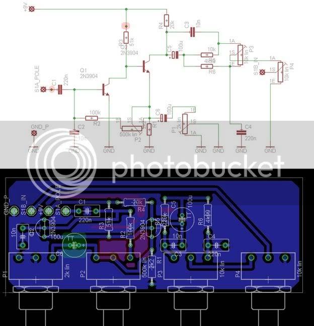
I chose to do a stompbox that is cheap, easy and useful: the Wooly Mammoth. I found the schematic and tried to make a pcb layout for it.
It is the first time I ever try to do anything like this, so I guess it will be full of errors :") : GO EASY ON ME!! ;D ;D
: GO EASY ON ME!! ;D ;D
I have attached a picture that shows the schematic and my pcb version. Can someone check it and point out any errors or signs of bad design or tips?
The 3-pin Molex are for connecting the pots (want them easily replaceable) and lots of input/output/switch/battery wiring is going to be off-board, so only the actual circuit is in the pcb and some holes in the upper-left corner for connections of +9V, ground, one pole of the bypass switch and one throw (the "circuit in" setting).
The components dimensions and lead spacing is based on actual products (checked with datasheet of each component)
Thanks a lot in advance for your help!! This place rocks!
EDIT: PICS REMOVED, SEE BELOW!!
I chose to do a stompbox that is cheap, easy and useful: the Wooly Mammoth. I found the schematic and tried to make a pcb layout for it.
It is the first time I ever try to do anything like this, so I guess it will be full of errors :
: GO EASY ON ME!! ;D ;DI have attached a picture that shows the schematic and my pcb version. Can someone check it and point out any errors or signs of bad design or tips?
The 3-pin Molex are for connecting the pots (want them easily replaceable) and lots of input/output/switch/battery wiring is going to be off-board, so only the actual circuit is in the pcb and some holes in the upper-left corner for connections of +9V, ground, one pole of the bypass switch and one throw (the "circuit in" setting).
The components dimensions and lead spacing is based on actual products (checked with datasheet of each component)
Thanks a lot in advance for your help!! This place rocks!
EDIT: PICS REMOVED, SEE BELOW!!