My first voltage multiplier PSU. 😎 (...for tube mics)

GroupDIY Audio Forum

Help Support GroupDIY Audio Forum:

This site may earn a commission from merchant affiliate links, including eBay, Amazon, and others.

rock soderstrom

Tour de France
Joined
Oct 14, 2009
Messages
3,548
Location
Berlin
Hi guys

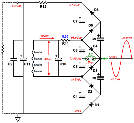
I have sketched a power supply based on a voltage multiplier for the first time.

The goal is to provide a flexible solution for tube microphones with transformers that are not dedicated tube transformers. I have numerous small 17V/8VA toroidal transformers that I would like to use for projects such as Sela T12, Royer mod or even Gyraf G7. Conceivable would be also 12V to 24V transformers, what one has available.

The Villard-Grainacher circuit provides taps from X2 to X6 which should then be routed via jumper to the filter section, as needed.

The heating is obtained from the same transformer, the thermal load is to be distributed to a large series resistor, the cooled LM317 and another filter resistor. The goal is a clean voltage of 4-12.6V.

Does this work as intended? What do you think? Ok, overkill or nonsense?

Cheers

20221107_233701.jpg
20221107_235906.jpg
Edit: intented for self etch PCBs. One will only populate what is needed
 
Last edited:
It looks like the DC filament supply will come from rectified 17Vac winding. The HV supply also comes from the 17Vac winding, but you show one end of the winding at 0V. Unless you half-wave rectify for the DC filament supply then the DC filament supply will not be solidly referenced to 0V.

I'd also suggest that the charging pulses required from the 17Vac winding (for both rectified dc supplies) will grossly drop the available ~24Vpk that you are hoping to get from that winding.
 
It looks like the DC filament supply will come from rectified 17Vac winding. The HV supply also comes from the 17Vac winding, but you show one end of the winding at 0V. Unless you half-wave rectify for the DC filament supply then the DC filament supply will not be solidly referenced to 0V.
Yes, I had planned to supply the DC heater voltage with its own bridge rectifier from the same 17VAC winding. Then a CRC filter and an adjustable textbook LM317 PSU which would be grounded at the output. Hmm, I guess that doesn't work that way, right? Would a half-wave rectifier change the situation? I just woke up, need to think about this again....

I'd also suggest that the charging pulses required from the 17Vac winding (for both rectified dc supplies) will grossly drop the available ~24Vpk that you are hoping to get from that winding.
Yes, there will be sagging. I think that is the nature of such a cascade. The question is how strong the whole sagging will be and whether I can get anywhere near my target voltages.
What can I do? More meaty transformer? According to my initial estimates, my 8VA model should be enough, since I'm only drawing a few mA on the B+ rail.

Thanks for your Feedback (y)
 
Last edited:
Perhaps feed the tripler through capacitors, to float ground reference and make fullwave rectification for heater possible

..just build it and see what happens irl, that tells you more than anything..

/Jakob E.
 
I could work around the problem by feeding the heater PSU with DC from the X2 tap. I think Dave Royer does it that way. Unfortunately, this also has the consequence that I have to burn even more VDC. (plus more sag)

Edit: schematic added
new-royer-schematic-2.gif
 
Last edited:
I could work around the problem by feeding the heater PSU with DC from the X2 tap. I think Dave Royer does it that way. Unfortunately, this also has the consequence that I have to burn even more VDC. (plus more sag)

Edit: schematic added
View attachment 100428
This one produces about 32V to power a 6V heater. Seriously?
 
The goal is to provide a flexible solution for tube microphones with transformers that are not dedicated tube transformers.
Indeed that's the problem. The voltage multiplier for B+ is not a big issue, considering teh low current draw.
The real issue is that the topology of the heater voltage must be adapted tpo the type of xfmr. For example a CT secondary will lend itself to full-wave rectification with grounded tap, when a non(CT secondary will request a bridge rectifier. Note that the voltage multiplier can work from such an arrangement.
Now, a 6V center-tap winding requires a bridge rectifier for producing about 8V unregulated, so requires a huge capacitor and no regulator (maybe an LDO?)
I would never consider using a voltage doubler for heaters, for it requires huge capacitors and introduces huge losses.
Your "universal" solution should include all these options.
 
Is it just a single heater of 6.3V, or a 12A?7 type heater, or multiple heaters life 2x EF86, or ....?

Aim would be to full-wave rectify for both the heater and the B+ supplies, rather than half-wave for each. For B+ supply, the winding can work in to a 'positive' capacitor input half-wave, and a 'negative' capacitor input half-wave - the winding then sees full wave rectification, and one leg of the winding sits at B+/2.
 
Aim would be to full-wave rectify for both the heater and the B+ supplies, rather than half-wave for each. For B+ supply, the winding can work in to a 'positive' capacitor input half-wave, and a 'negative' capacitor input half-wave - the winding then sees full wave rectification
It would be the same with the negative side of the voltage multiplier grounded. Don't let the (apparent) lack of symmetry fool you.
and one leg of the winding sits at B+/2.
Then the heater voltage would be elevated at B+/2 also. It may or may not be acceptable for the tube.
 
Another option to add to the grab bag of possibilities:
https://tubecad.com/2013/03/blog0258.htm
12AU7%20Aikido%2018Vac%20Power%20Supply.png
 
Is it just a single heater of 6.3V, or a 12A?7 type heater, or multiple heaters life 2x EF86, or ....?
Just a single heater, 4 - 6,3V with an optional 12,6V I probably will never use.

For 5840, 6S6B, 6AK5, EC71 and similar with the option to underheat. 6072 and ECC81 are the only 12,6V tubes on my wishlist for mic projects.
 
The real issue is that the topology of the heater voltage must be adapted tpo the type of xfmr. For example a CT secondary will lend itself to full-wave rectification with grounded tap, when a non(CT secondary will request a bridge rectifier. Note that the voltage multiplier can work from such an arrangement.
Now, a 6V center-tap winding requires a bridge rectifier for producing about 8V unregulated, so requires a huge capacitor and no regulator (maybe an LDO?)
I would never consider using a voltage doubler for heaters, for it requires huge capacitors and introduces huge losses.
Your "universal" solution should include all these options
I'll have to think it all through first and see what that means for my project.

Thanks for your feedback and ideas!
 
The real issue is that the topology of the heater voltage must be adapted tpo the type of xfmr. For example a CT secondary will lend itself to full-wave rectification with grounded tap, when a non(CT secondary will request a bridge rectifier. Note that the voltage multiplier can work from such an arrangement.
This is at the moment for me the most promising approach so far to burn as little energy as possible under the following guidelines and goals.

- only one standard mains transformer with one winding,
- adjustable DC heating in the range 4V - 12,6V
- B+ minimum 60V up to 120V, if more than 120 are possible, nice!
- by jumper adjustable B+
- good heat distribution
- very clean B+ and filament voltage

Ergo, according to Abbey and Jacob I would use a bridge rectifier for the heater with my existing transformer, protected by a fuse. Then a CRC filter and a textbook LM317 PSU followed by another CRC filter. This would successfully do the heating for the tube.

The Villard-Grainacher circuit then branches off at the bridge rectifier and does its magic as drawn in the sketch above. Since both power supplies are connected to the same reference ground, everything is fine. Right?

Anything else to consider?

In my opinion this is the solution with the least wasted energy, it will still get warm, but I could live with it ernergetically. It won't win a prize for efficiency, but hopefully it will keep the climate activists of the "last generation" from sticking themselves to my front door. ;)
 
Last edited:
Then the heater voltage would be elevated at B+/2 also. It may or may not be acceptable for the tube.
OP has stated B+ is 120V max - all identified valves have a Vhk rating exceeding 60V. Just the action of elevating the heater may sufficiently suppress ac hum if the heater was directly ac powered, but if that path was followed then OP would need to confirm that layout and other factors don't cause measurable hum because of the ac heater powering.
 

Latest posts

Back
Top